USO
RESTRITO
Signal Selection
89
Ch
a
p
te
r 3
S
ig
n
a
l S
e
le
c
ti
o
n
and
T
ra
n
s
itio
n
s
Signal Selection
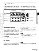
You carry out signal selection with the cross-point buttons
in the cross-point control block of each M/E bank or the
PGM/PST bank, and the buttons in the auxiliary bus
control block.
The number of buttons in each cross-point row may be 16,
24, or 32, but here the description is of the 32-button case
as an example.
Cross-point buttons
Reentry buttons
Key 1 row
KEY3 button
Key 2 row
KEY4 button
Source name displays
Background A row
Background B row
Dedicated SHIFT
button
UTIL button
Reentry buttons
Cross-point control block
Basics of Signal Selection
The M/E banks, PGM/PST bank, and auxiliary bus control
block each have 32 cross-point buttons and three reentry
buttons (four in the case of the auxiliary bus control block).
These buttons are identified by numbers common to all of
the banks and the control block, and a signal is assigned to
each number.
The basis of signal selection is to select, in a cross-point
button row, the cross-point button to which is assigned the
desired signal.
Reentry buttons
To use the output of one M/E bank as the input signal to
another bank, use the reentry buttons [M/E 1], [M/E 2],
and [M/E 3] (on the auxiliary bus control block, [M/E 1],
[M/E 2], [M/E 3], and [PGM]) in the cross-point control
block of the destination bank.
For example, to feed the output from the M/E-1 bank as the
background B input to M/E-2, in the M/E-2 cross-point
control block, press the [M/E 1] button in the background
B row.
Notes
•
To select [M/E 4] or [M/E 5], it is necessary to assign M/
E 4 or M/E 5 to a button
•
For a 5M/E or 6M/E system, a maximum of four reentry
stages are possible. For other restrictions on reentry,
Bus Selection
Each row of 32 cross-point buttons is shared by multiple
buses.
To assign a bus to the cross-point buttons in the auxiliary
bus control block, press one of the AUX delegation buttons
to select the bus.
Notes
•
When using the CCP-6224/6324, buses may be assigned
with the cross-point button rows for keys 1 and 2 as the
auxiliary bus control block.
Summary of Contents for MVS-8000X SystemMVS-7000X System
Page 358: ...USO RESTRITO 358 Wipe Pattern List Appendix Volume 1 Enhanced Wipes Rotary Wipes ...
Page 360: ...USO RESTRITO Random Diamond DustWipes 360 1 w pe PaternLO ...
Page 362: ...USO RESTRITO 362 DME Wipe Pattern List Appendix Volume 1 Door 2D trans 3D trans ...
Page 364: ...USO RESTRITO 364 DME Wipe Pattern List Appendix Volume 1 Page turn Page roll ...
Page 377: ...USO RESTRITO Menu Tree 377 Appendix Volume 1 AUX Menu AUX button CCR Menu CCR button ...
Page 379: ...USO RESTRITO Menu Tree 379 Appendix Volume 1 DME Menu DME button ...
Page 381: ...USO RESTRITO Menu Tree 381 Appendix Volume 1 Macro Menu MCRO button ...
Page 382: ...USO RESTRITO 382 Menu Tree Appendix Volume 1 Key Frame Menu KEY FRAME button ...
Page 383: ...USO RESTRITO Menu Tree 383 Appendix Volume 1 Effect Menu EFF button ...
Page 384: ...USO RESTRITO 384 Menu Tree Appendix Volume 1 Snapshot Menu SNAPSHOT button ...
Page 385: ...USO RESTRITO Menu Tree 385 Appendix Volume 1 Shotbox Menu SHOTBOX button ...
Page 386: ...USO RESTRITO 386 Menu Tree Appendix Volume 1 File Menu FILE button ...
Page 391: ...USO RESTRITO Menu Tree 391 Appendix Volume 1 ENG SETUP button to previous pages ...
Page 413: ...USO RESTRITO MVS 8000X System MVS 7000X System SY 4 470 637 01 1 Sony Corporation 2013 ...
Page 706: ...USO RESTRITO MVS 8000X System MVS 7000X System SY 4 470 637 01 1 Sony Corporation 2013 ...


