USO
RESTRITO
Settings Relating to Signal Inputs (Input Menu)
635
Ch
a
p
te
r 21
DM
E
S
e
tu
p
(D
M
E
)
DME Setup (DME)
Chapter
21
Settings Relating to
Signal Inputs (Input
Menu)
To make settings relating to DME input signals, display
the DME >Input menu.
To display the Input menu
In the Engineering Setup menu, select VF4 ‘DME’ and
HF1 ‘Input.’
The status area shows the initial crop information and the
DME system phase.
The following functions are available here.
•
Initial Crop:
Make the initial crop setting.
•
Matte Illeg. Color Limit:
Switch the illegal limiter for
the signal generated by the DME internal matte
generator on or off.
•
System Phase:
Adjust the operation timing of the whole
system with respect to the reference signal.
•
TBC Center:
Set the TBC window center position.
When the signal format is 1080P, up to four DMEs can be
operated (DME1 to DME4).
In the following description, the settings for DME1 are
given by way of example, but the settings for DME2 to
DME4 are carried out in a similar way.
If you selected 4:3 in step
1
Knob
Parameter
Adjustment
Setting values
1
Top
Position of top
side
–3.00 to +3.00
2
Left
Position of left
side
–4.00 to +4.00
3
Right
Position of right
side
–4.00 to +4.00
4
Bottom
Position of
bottom side
–3.00 to +3.00
If you selected 16:9 in step
1
Knob
Parameter
Adjustment
Setting values
1
Top
Position of top
side
–9.00 to +9.00
2
Left
Position of left
side
–16.00 to
+16.00
3
Right
Position of right
side
–16.00 to
+16.00
4
Bottom
Position of
bottom side
–9.00 to +9.00
To return the parameter values to their default values
Press [Unity] in the <Crop> group.
Setting an Illegal Color Limit for
Matte Signals
To enable the illegal color limiter for the signals generated
Setting the Initial Crop
1
In the DME1 <Aspect> group of the DME >Input
menu, select the screen aspect ratio (16:9 or 4:3).
2
In the DME1 <Crop> group, press [Initial Crop] and
adjust the following parameters.
by the DME internal matte generator, press [Matte Illeg
Col Limit] for DME1 in the DME >Input menu, turning it
on.
Making DME System Phase
Adjustment
To adjust the DME reference phase, use the following
procedure.
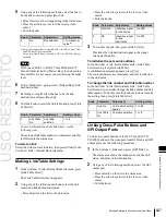
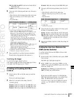
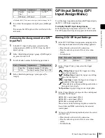
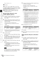
Summary of Contents for MVS-8000X SystemMVS-7000X System
Page 358: ...USO RESTRITO 358 Wipe Pattern List Appendix Volume 1 Enhanced Wipes Rotary Wipes ...
Page 360: ...USO RESTRITO Random Diamond DustWipes 360 1 w pe PaternLO ...
Page 362: ...USO RESTRITO 362 DME Wipe Pattern List Appendix Volume 1 Door 2D trans 3D trans ...
Page 364: ...USO RESTRITO 364 DME Wipe Pattern List Appendix Volume 1 Page turn Page roll ...
Page 377: ...USO RESTRITO Menu Tree 377 Appendix Volume 1 AUX Menu AUX button CCR Menu CCR button ...
Page 379: ...USO RESTRITO Menu Tree 379 Appendix Volume 1 DME Menu DME button ...
Page 381: ...USO RESTRITO Menu Tree 381 Appendix Volume 1 Macro Menu MCRO button ...
Page 382: ...USO RESTRITO 382 Menu Tree Appendix Volume 1 Key Frame Menu KEY FRAME button ...
Page 383: ...USO RESTRITO Menu Tree 383 Appendix Volume 1 Effect Menu EFF button ...
Page 384: ...USO RESTRITO 384 Menu Tree Appendix Volume 1 Snapshot Menu SNAPSHOT button ...
Page 385: ...USO RESTRITO Menu Tree 385 Appendix Volume 1 Shotbox Menu SHOTBOX button ...
Page 386: ...USO RESTRITO 386 Menu Tree Appendix Volume 1 File Menu FILE button ...
Page 391: ...USO RESTRITO Menu Tree 391 Appendix Volume 1 ENG SETUP button to previous pages ...
Page 413: ...USO RESTRITO MVS 8000X System MVS 7000X System SY 4 470 637 01 1 Sony Corporation 2013 ...
Page 706: ...USO RESTRITO MVS 8000X System MVS 7000X System SY 4 470 637 01 1 Sony Corporation 2013 ...


