USO
RESTRITO
568
Overall Control Panel Settings (Config Menu)
Ch
a
p
te
r 19
Co
n
tr
o
l P
a
n
e
l S
e
tu
p
(P
a
n
e
l)
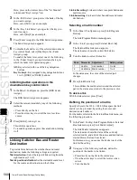
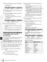
Here, press on the intersection of the “1st Module”
column and “Key1 Assign” row.
3
In the <M/E Select> group, select the bank of the key
you want to assign.
Here, select [M/E-1] as an example.
4
In the <Key Link Select> group, select the key you
want to assign.
Here, select [Key4] as an example.
5
Press [Fader Assign] in the DSK Fader Assign menu.
The Fader Assign menu appears.
6
To disable the fader lever of the selected downstream
key control block, select [Disable] in the <Fader
Assign> group.
To enable the fader lever, select one of the following
in the <Fader Assign> group, determine the key to
which the fader lever operation applies.
All:
Key selected with one of the key delegation
buttons
Key1 to Key4:
Key assigned to key delegation buttons
1 to 4 ([DSK1] to [DSK4] buttons)
Inhibiting button operations in the
downstream key control block
1
In the Panel >Config menu, press the [DSK Fader
Assign].
The DSK Fader Assign menu appears.
2
Select the relevant module by any of the following
methods.
•
Press directly on the list.
•
Press the arrow keys to scroll the reverse video
cursor.
3
Press [Inhibit], turning it on.
This inhibits operations.
To reenable operations, press the same button, turning
it off.
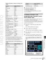
Linking Switcher Bus and Router
Destination
To provide links between the switcher bus and router
destination, make the following settings as required.
Matrix selection:
Select the target of link setting from the
eight matrices (1 to 8).
Matrix position definition:
Set the start address and level
for the source and destination on the S-Bus.
Link table setting:
Link a switcher cross-point button and
matrix source.
Link bus setting:
Link a switcher bus address and router
destination.
Selecting a matrix number
1
In the Panel >Config menu, press [Link/Program
Button].
The Link/Program Button menu appears.
2
In the <Link> group, press [External Bus Link].
The External Bus Link menu appears.
The status area shows the current link status.
3
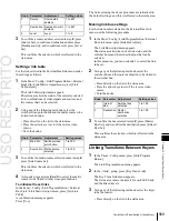
Turn the knobs to select the matrix.
Knob
Parameter
Adjustment
Setting values
1
Link No
Link number
1 to 64
2
Link Matrix Matrix number
1 to 8
In the status area, the color of the selected part
changes.
4
Press [Link Matrix Set].
This confirms the matrix selection and the selected
part in the status area returns to the previous color.
To delete a link
With the link selected, press [Clear].
Defining the position of a matrix
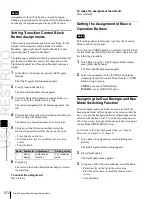
Specify where in the 1024 × 1024 S-Bus space the link
matrix is to be provided, by setting the source and
destination start address.
For the matrix selected in the External Bus Link menu, use
the following procedure.
1
In the Panel >Config >Link/Program Button >External
Bus Link menu, press [Link Matrix Adjust].
The Link Matrix Adjust menu appears.
The status area shows the status of the currently
selected matrix, and a list of the source and destination
start addresses that can be selected.
In this menu too, you can use the knobs to select the
link for the setting.
2
Using any of the following methods, define the
position of the matrix to be linked.
•
Press directly on the list in the status area.
•
Press the arrow keys to scroll the reverse video
cursor.
•
Turn the knobs.
Summary of Contents for MVS-8000X SystemMVS-7000X System
Page 358: ...USO RESTRITO 358 Wipe Pattern List Appendix Volume 1 Enhanced Wipes Rotary Wipes ...
Page 360: ...USO RESTRITO Random Diamond DustWipes 360 1 w pe PaternLO ...
Page 362: ...USO RESTRITO 362 DME Wipe Pattern List Appendix Volume 1 Door 2D trans 3D trans ...
Page 364: ...USO RESTRITO 364 DME Wipe Pattern List Appendix Volume 1 Page turn Page roll ...
Page 377: ...USO RESTRITO Menu Tree 377 Appendix Volume 1 AUX Menu AUX button CCR Menu CCR button ...
Page 379: ...USO RESTRITO Menu Tree 379 Appendix Volume 1 DME Menu DME button ...
Page 381: ...USO RESTRITO Menu Tree 381 Appendix Volume 1 Macro Menu MCRO button ...
Page 382: ...USO RESTRITO 382 Menu Tree Appendix Volume 1 Key Frame Menu KEY FRAME button ...
Page 383: ...USO RESTRITO Menu Tree 383 Appendix Volume 1 Effect Menu EFF button ...
Page 384: ...USO RESTRITO 384 Menu Tree Appendix Volume 1 Snapshot Menu SNAPSHOT button ...
Page 385: ...USO RESTRITO Menu Tree 385 Appendix Volume 1 Shotbox Menu SHOTBOX button ...
Page 386: ...USO RESTRITO 386 Menu Tree Appendix Volume 1 File Menu FILE button ...
Page 391: ...USO RESTRITO Menu Tree 391 Appendix Volume 1 ENG SETUP button to previous pages ...
Page 413: ...USO RESTRITO MVS 8000X System MVS 7000X System SY 4 470 637 01 1 Sony Corporation 2013 ...
Page 706: ...USO RESTRITO MVS 8000X System MVS 7000X System SY 4 470 637 01 1 Sony Corporation 2013 ...


