background image

USO 

RESTRITO

Names and Functions of Parts of the Control Panel 

57 


Ch
a

p

te

r 2

  M

e

n

u

s

 and

 Co
n

tr

o

l P

a

n

e

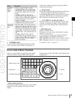
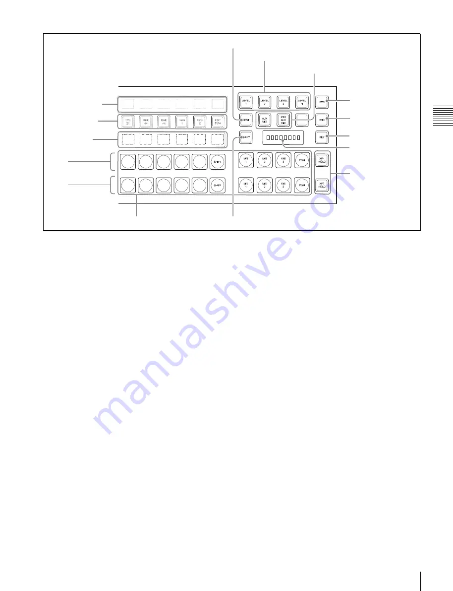
DEST button 

Level selection buttons 

AUX mix buttons 


Selected source 

name displays 

AUX delegation 

buttons 

Source name 

displays 

RTR button 


2ND button 


KEY button 

Selected bus display 


1st 


2nd 


XPT HOLD buttons 


Cross-point buttons 

SHIFT button 


a


AUX delegation buttons


Press one of these buttons, turning it on, to select the bus 
to which to assign the cross-point buttons in the auxiliary 
bus control block. 


For buses that can be selected, see “Bus Selection” (page 
89).


b


Selected source name displays


These show the name of the currently selected signal 
(source) on the bus corresponding to the delegation button. 


c


DEST (destination) button


Press this button, turning it on, to display the names of 
buses allocated to the delegation buttons in the selection 
source name displays. 
In the case of a module without selected source name 
displays, this button is invalid. 


d


Selected bus display


This shows the name of the bus selected by the auxiliary 
bus delegation buttons. 


e


Cross-point buttons


The cross-points in the auxiliary bus control block are 
arranged in two rows: an upper row (1st row) and a lower 
row (2nd row), and are allocated to the buses selected with 
the AUX delegation buttons. The 1st row contains the 
cross-point buttons for unshifted buses, and the 2nd row 
contains the cross-point buttons for shifted buses. 
When the DME 1 V/K to DME 8 V/K buses are selected 
with the AUX delegation buttons, the 1st row cross-point 
buttons are for the currently showing side of DME, and the 
2nd row are for the reverse side. 

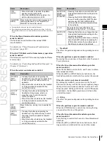
By holding down the [2ND] button and making an AUX 
delegation selection, you can allocate the 2nd row to a 
different bus from the 1st row. 
In this case, if the 32nd button is set to be a [SHIFT] button 
(in a 32-button system), you can select the shifted cross- 
point buttons in the 1st and 2nd rows. 


f


XPT HOLD (cross-point hold) buttons


Press one of these buttons, turning it on, to enable cross- 
point hold. 


g


KEY button


While this button is held down, you can use the cross-point 
row of buttons to select key signals. 


h


2ND button


After selecting a bus with an AUX delegation button, hold 
down this button, and select another AUX delegation, thus 
allocating a different bus in the 2nd row from the 1st row. 


i


Source name displays


These show the names of the source signals which can be 
selected by the cross-point buttons. While the [SHIFT] 
button is enabled, the shifted signal name is displayed. If a 
different bus is allocated to the 2nd row, while the [2ND] 
button is held down, the 2nd row signal name is displayed. 
While the [KEY] button is held down, the source name of 
the key signal assigned to the cross-point buttons appears. 


j


SHIFT button


While this button is enabled, the shifted signal names 
appear in the source name display. Pressing this buttons 
toggles the source name display between the shifted signal 
names and unshifted signal names. 

Summary of Contents for MVS-8000X SystemMVS-7000X System

Page 1: ...USO RESTRITO Multi Format Switcher System MVS 8000X System MVS 7000X System With CCP 8000 Series Center Control Panel User s Guide Volume 1 English Software Version 12 10 and Later 1st Edition Revised 2 ...

Page 2: ...RANTIES OF MERCHANTABILITY OR FITNESS FOR ANY PARTICULAR PURPOSE WITH REGARD TO THIS MANUAL THE SOFTWARE OR SUCH OTHER INFORMATION IN NO EVENT SHALL SONY CORPORATION BE LIABLE FOR ANY INCIDENTAL CONSEQUENTIAL OR SPECIAL DAMAGES WHETHER BASED ON TORT CONTRACT OR OTHERWISE ARISING OUT OF OR IN CONNECTION WITH THIS MANUAL THE SOFTWARE OR OTHER INFORMATION CONTAINED HEREIN OR THE USE THEREOF Sony Corp...

Page 3: ...ns AUX MIX 3232 Chapter Chapter transitions 7333 12 3 20 Chapter 8 Functions relating to the switcher Classifi cation Functions supported Menu No See page Vol 1 Vol 2 M E 6M E system 7316 11 Chapter Chapter banks support a 82XX 2 19 86XX Chapter 10 Format converter Frame synchronizer 7313 4 Chapter 18 720P frame delay function support 7313 4 Chapter 18 External device control Odetics protocol supp...

Page 4: ...With Simple Transition Modules 31 Control Panel Example Configuration 3 With Compact Transition Modules 32 Cross Point Control Block 32 Cross Point Control Block in Key AUX Bus Delegation Mode 36 Transition Control Block Standard Type 37 Flexi Pad Control Block Standard Type 40 Key Control Block 42 Device Control Block Trackball 45 Device Control Block Joystick 48 Device Control Block Search Dial ...

Page 5: ...Transitions Video Processing Flow 88 Signal Selection 89 Basics of Signal Selection 89 Bus Selection 89 AUX Panel less Function 92 SignalAssignmentandSelection 92 Signal Name Display 94 Transitions 95 SelectingtheNextTransition 95 Transition Types 95 Procedure for Basic Transition Operation 96 Key Priority Setting 98 Setting the Key Priority in the Transition Control Block 98 Setting the Key Prior...

Page 6: ... Control Block 144 Key Edge Modifications 144 Masks 146 Applyinga DMEEffect toaKey 146 Other KeySetting Operations 148 Key Adjustments Multifunction Flexi Pad Control Block 149 Resizer 152 Two Dimensional Transformations and Rotation of Keys 152 Resizer Interpolation Settings 155 Resizer Crop BorderSettings 155 Applying Resizer Effects 156 Setting rotation of the resizer 159 Key Snapshots 160 Key ...

Page 7: ...Selecting the DME Wipe Pattern 200 Editing the DME Wipe Pattern 200 Saving Canceling and Deleting DME Wipe Snapshots 201 Chapter 7 Frame Memory Overview 202 Still Image Operations 204 Preparations 204 Interpreting the Frame Memory Menu 204 Selecting an Input Image 206 Selecting Outputs and Target Frame Memory 207 Capturing and Saving an Input Image 207 Recalling Still Images 209 Image Output 210 C...

Page 8: ...l Color Corrector Operations 241 Enabling Color Corrector 241 Copy and Swap Operations 241 Color Corrector Functions 242 Input Video Processing Operations 242 Primary Color Correction Operations 242 Secondary Color Correction Operations 245 LuminanceProcessingOperations 245 Spot Color Adjustment 246 OutputVideoProcessingOperations 247 YUV Clip Operations 248 RGB Clip Operations 248 Chapter 10 Spec...

Page 9: ...07 Mosaic Settings 307 Sketch Settings 307 Metal Settings 309 Dim and Fade Settings 309 Glow Settings 310 Mask Settings 310 Freeze Settings 312 Applying Special Effects Nonlinear Effect Settings 313 Wave Settings 313 Mosaic Glass Settings 315 Flag Settings 315 Twist Settings 315 Ripple Settings 316 Rings Settings 319 Broken Glass Settings 319 Flying Bar Settings 320 Blind Settings 320 Split Settin...

Page 10: ...380 Device Menu 380 Macro Menu 381 Key Frame Menu 382 Effect Menu 383 Snapshot Menu 384 Shotbox Menu 385 File Menu 386 Engineering Setup Menu 387 User Setup Menu 392 Diagnostic Menu 392 Disabled Operation and Settings Menus 393 Using the M E 4 or M E 5 Bank 396 Assigning a Button for M E 4 or M E 5 Selection in the Setup Menu 396 Using Keys 5 to 8 397 Assigning Buttons for Selection of Keys 5 to 8...

Page 11: ...Copying 452 Pause 453 Keyframe Loop Repeated Execution of a Specified Range 453 UndoinganEditOperation 454 DurationModeSetting 454 Transition Mode Settings for User Programmable DME 454 Keyframe Creation and Editing in the Multifunction Flexi Pad Control Block 457 Time Settings 458 SettingtheKeyframeDuration 458 SettingtheEffectDuration 459 Setting the Delay 459 Path Settings 460 BasicProcedurefor...

Page 12: ...ing a Shotbox Register in the Numeric Keypad Control Block 489 Creating a Shotbox Register in the Multifunction Flexi Pad Control Block 490 Creating a Shotbox Register Using the Menus 491 Shotbox Execution 493 Shotbox Execution From the Numeric Keypad Control Block 493 Shotbox Execution in the Flexi Pad Control Block or the Multifunction Flexi Pad Control Block 493 Shotbox Execution in the Utility...

Page 13: ...ch Saving Files 539 Batch Loading Files 539 Batch Copying Files 539 Importing and Exporting Files 540 DisplayingtheImport ExportMenu 540 ImportingFrameMemoryData 540 ExportingFrameMemoryData 541 DirectoryOperations 542 DisplayingtheDirectoryMenu 542 CreatingaNewDirectory 542 RenamingaDirectory 542 DeletingaDirectory 542 Copying Files Between Different Unit IDs 543 SavingFilesRecalledbyAutoload 544...

Page 14: ...gion Selection Buttons in the Numeric Keypad Control Block or Multifunction Flexi Pad Control Block 570 Setting Transition Control Block Button Assignments 572 Setting the Assignment of Macro Operation Buttons 572 Assigning the Dual Background Bus Mode Switching Function 572 Assigning the Utility Shotbox Mode Switching Function 573 Assigning the Function to Disable Cross Point ButtonOperations toa...

Page 15: ...ngSettingsRelatingtoEffects 603 Setting the First Keyframe When a Rewind is Executed 603 Setting the Source and Destination Names 603 Settings for the Flexi Pad and Wipe Snapshot Menu 604 SettingtheButtonOperationMode 604 Setting the Operation Mode of the ALL Button in the Transition Control Block 605 Setting Trackball Joystick Search Dial and Double Click Sensitivity 605 SpecifyingMainSplitFader ...

Page 16: ...e Menu 630 Making 9 Pin Port Device Interface Settings 630 Making Switcher Processor GPI Input Settings 631 Making Switcher Processor GPI Output Settings 632 Enabling or Disabling AUX Bus Control 633 Setting the Interface Between the DME and the Switcher 633 Setting the AUX Bus Output and Reentry Input 634 Selecting the Mode for Turning Off Keys Upon Receiving the Editor Command 634 Chapter 21 DME...

Page 17: ...y Copy Settings Tally Copy Menu 656 Making New Tally Copy Settings 656 Modifying Tally Copy Settings 656 Deleting Tally Copy Settings 657 Parallel Tally Settings Parallel Tally Menu 657 Making or Modifying Parallel Tally Settings 657 Deleting Parallel Tally Settings 658 Serial Tally Settings Serial Tally Menu 658 Setting or Changing the Serial Tally Settings 658 Making the Serial Tally Source Addr...

Page 18: ...ary Bus Control Block 674 Other Blocks 675 Menu Operations Not Recorded in a Menu Macro 676 Data Saved by Setup Define and Initial Status Define 677 Data Saved by Setup Define 677 Data Saved by Initial Status Define 681 Error Messages 684 Error Messages Displayed in the Error Status Error Log Menu 684 Error Messages Appearing in a Message Box 685 Error Messages Shown in the Error Information Menu ...

Page 19: ...stem configurations must be drawn the terms in the following table are used Principal components and naming The formal product names of the principal components of the MVS 8000X 7000X system and the terms used in this manual are as follows System nomenclature The following terms are used for systems depending on the combination of installed options and the signal format System configuration and fe...

Page 20: ...hannels of DME functionality When the signal format is 1080P you can also connect up to four MVE 8000A units which provides a maximum of eight channels of DME functionality For the MVS 7000X by installing the optional MKS 7470X 7471X DME board set you can use a maximum of four channels of DME functionality You can use a maximum of eight channels of DME functionality in the whole switcher system Po...

Page 21: ...d shotbox control blocks have color backlit LCD displays The signal names and graphical representations of the patterns associated with buttons provide intuitive feedback and allow the immediate decisions that are required in a live operating environment Basic Video Processing This section introduces basic functions used for video Transitions In the M E banks and PGM PST bank the switch from the c...

Page 22: ...hanging the background and keys Youcanchangeanyofthe eightkeys downstreamkeys on the PGM PST bank and the background at the same time Key 1 Transition Insert Delete Key 2 Key 1 Changing the background and key 2 simultaneously Key 2 Key 1 Inserting or deleting key 1 and key 2 Key 2 Key 1 Transition Transition Key 3 Key 4 Key 2 Deleting key 1 and inserting key 2 Changing the background and keys 1 to...

Page 23: ...as an example Video used in the transition Background A Background B Transition type wipe Same wipe is appliedto background and key Effect of a common transition Effect of use with an independent key transition The key is inserted with an independent key transition as the background changes with a common transition providing the following result Transition type wipe Independent key transition type...

Page 24: ...for a wipe are as follows Standard wipe patterns Enhanced wipes Rotary wipes Mosaic wipe pattern Random and diamond dust wipe patterns You can combine two selected patterns referred to as main and sub to create a new pattern pattern mix You can also specify the wipe direction or set the pattern position applying various changes and modifiers to the selected wipe pattern For details see Wipes page ...

Page 25: ...in hue black level of the input video signal There are two types of adjustment adjustment of an individual input signal and adjustment as image effects on a particular bus For details see Video Process page 238 Turn the side flag function on Side flag area Side flag area For details see Side Flags page 250 Multi Program 2 By operating the switcher in Multi Program 2 mode a Color Corrector The colo...

Page 26: ...00X and the DME upgrade software in an MVE 8000A MVE 9000 or MKS 7470X 7471X enables the processing of video in 3D mode For details see 3D Support page 260 Key Key 1 to Key 8 are available on the main side Program output for Sub Background B signal from utility 3 bus Background A signal from utility 2 bus Key Key 2 to Key 8 are available on the sub side For details see Multi Program 2 page 253 ...

Page 27: ...d VTR Abekas A53 protocol For details on the devices that can be connected consult your Sony representative You can control an external device by previously registering timeline keyframes For details see Chapter 12 External Devices Volume 2 Keyframes A keyframe represents an instantaneous state of an image it can be saved in a register and recalled for reuse By arranging a number of keyframes on t...

Page 28: ...e register data including setup information and snapshot information as a file on a hard disk or memory card and recall it as required Utility The utility function refers to a function whereby you can assign an arbitrary action or a shortcut for frequently used menu to a particular button then instantly recall the action or menu by pressing the button For details see Utility Execution in Chapter 1...

Page 29: ... following headings System setup System For details see Chapter 18 System Setup Volume 2 Panel setup Panel For details see Chapter 19 Control Panel Setup Panel Volume 2 Switcher setup Switcher For details see Chapter 20 Switcher Setup Switcher Volume 2 DME setup DME Fordetails seeChapter21 DME Setup DME Volume 2 DCU setup DCU For details seeChapter22 DCUSetup DCU Volume 2 Router tally setup Router...

Page 30: ...ation and settings are disabled even if they appear in the menu See Disabled Operation and Settings Menus page 393 in Appendix To select M E 4 or M E 5 using control panel buttons it is first necessaryto assign the buttons in the Setup menu For details of assignment see Assigning a Button for M E 4 or M E 5 Selection in the Setup Menu page 396 in Appendix Control Panel Example Configuration 1 With...

Page 31: ...pe page 37 Downstream key control block page 66 Numeric keypad control block page 54 Fade to black control block page 56 Flexi Pad control block standard type page 40 Control panel configuration 1 with standard transition modules Control Panel Example Configuration 2 With Simple Transition Modules The following illustration shows a typical configuration with simple transition modules used in the t...

Page 32: ...Control panel configuration 3 with compact transition modules Cross Point Control Block In the cross point control block you can select the signals to be used in this M E bank or PGM PST bank There are also modules without the source name displays shown in the following figure All operations except those of the SHIFT button are the same as for a module with source name displays Notes In the case o...

Page 33: ...l on that bus Chapter 2 Menus and Control Panel Key 2 row Reentry buttons Key 1 row 1 Cross point buttons 7M Ebankdisplay 3Keybusselectionbuttons Background B row Reentry buttons 8Macrobuttons Background A row 5 Source name displays 6 Dedicated SHIFT button 4UTILbutton 2XPTHOLDbuttons a Cross pointbuttons These buttons select the signals used for video creation on this M E bank or PGM PST bank Eac...

Page 34: ...ng a Key or AUX Bus to a Button in the Key 1 or Key 2 Row in Chapter 19 Volume 2 b XPT cross point HOLD buttons Turning one of these buttons on enables you to recall a keyframe or snapshot while keeping the current cross point selection unchanged Function of this button varies depending on the operation mode selected in the Setup menu For details see Selecting the Bank to Make the Settings in Chap...

Page 35: ... Panel Every time the button is pressed it toggles between the on and off states for key 1 and key 2 rows For background A and background B rows utility buses remain disabled e Source name displays These show the names of the signals which can be selected on the cross point buttons in two or four characters or in auto mode While the SHIFT button on the right hand side or the SHIFT button assigned ...

Page 36: ...an select the cross point of the key source bus When you select a cross point while holding down the button to which anyof DME 1 V K to DME 4 V K buses is assigned in the Key AUX delegation button row you can select the image on the reverse side of the currently viewed DME image c Source name bus name display for key AUX buses When the DSPLY button is on these show the names of the signals corresp...

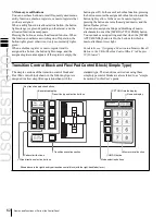
Page 37: ... Type In the transition control block you can modify the output of the M E bank or PGM PST bank and perform transitions Both common transition and independent key transition operations are possible 9PRIORSETbutton 1Next transition selection buttons 8Keystatusdisplay 2Transition type selection buttons q Keydelegationbuttons qdKey source name display key snapshot buttons qf Key snapshot setting butt...

Page 38: ... inserts or removes downstream keys 1 to 8 For details of assignment and selection of keys 5 to 8 see the following sections in Appendix Assigning Buttons for Selection of Keys 5 to 8 in the Setup Menu page 397 and Selecting Keys 5 to 8 for Next Transition page 398 KEY PRIOR priority When this button is lit the setting of the key priority after the next transition is enabled The key priority after...

Page 39: ...nce the video changes during the transition on the preview output from the M E or PGM PST bank During the preview you can use the fader lever AUTO TRANS button and CUT button One of the following functions of this button can be selected in a Setup mode When the transition completes the system returns to the normal mode The transition preview mode is maintained while this button is pressed Switchin...

Page 40: ...to 8 in the Setup Menu page 397 in Appendix Name Description KEY1 ON to KEY8 ON DSK1 ON to DSK8 ON in the PGM PST bank Press the corresponding one of these buttons to cut key 1 to key 4 in or out instantaneously When the key corresponding to the button appears in the final program output the button lights red and otherwise lights amber AUTO TRANS transition These correspond to keys 1 to 4 from lef...

Page 41: ...k selection After pressing this button press a button in the memory recall section to select banks 0 to 9 Name Description WIPE To save or recall a wipe snapshot or recall the pattern number of a wipe pattern use this in combination with the buttons of the memory recall section DME To save or recall a DME wipe snapshot or recall the pattern number of a DME wipe pattern use this in combination with...

Page 42: ...ol Panel e XPT HOLD cross point hold status display A bus for which cross point hold is set appears as a green light f Numeric display Depending on the operation mode this shows the pattern number of a wipe or DME wipe a bank number a register number a transition rate and so on in up to four digits Key Control Block Each of the M E banks and the PGM PST bank includes eight keyers for keys 1 to 8 a...

Page 43: ... button turning it on To select the signal on the key source bus hold down this button and press a button in the key 1 or key 2 row in the cross point control block To use the signal selected on the key fill bus as key source self keying press the AUTO SEL button and SPLIT button at the same time so that both are off MATTE FILL To use a color matte from the internal generator as key fill press thi...

Page 44: ...rom amber to green and the fifth and subsequent parameters are assigned to the knobs allowing them to be adjusted f SHOW KEY button While this button is held down a keyprocessed keysource signal is output from the specified output port You can make the output specification independently for the edit preview and the preview of each M E or PGM PST bank in the Setup menu g Knobs Turn the knobs to adj...

Page 45: ...ated to anotherkeyer or transition hold down this button and press the correspondingDME channel selection button to switch to the state in which the keyer or transition to which the DME channel is allocated is currently selected n AUTO DELEG auto delegation button When this button is on the key delegation selection state of the key control block is linked to the key delegation selection state of t...

Page 46: ...ction button K1RSZ to K8RSZ Chapter 2 Menus and Control Panel Selected buttons Overview of assigned operation FX CTRL Leave this button off for operation Alternatively for details of operation of this button refer to the help information for the MPES FX01 Programmable Effector software b Operationbuttons The following buttons are used to carry out the corresponding operations Function of each butt...

Page 47: ...o 50 00 CLR WORK BUFR Press this button twice in rapid succession to reset all parameters on the target M E or PGM PST to their initial values a Among these buttons you can select multiple buttons b By setting the operation mode in setup you can select keys 5 to 8 with these buttons In this case it is not possible to select more than one of keys 1 to 8 When the three dimensional transform operatio...

Page 48: ...his makes it possible to carry out timeline start stop point setting operation for the device selected with the device selection buttons timeline setting mode Device Control Block Joystick All functions of the joystick type device control block are equivalenttothefunctionsofthetrackballtype exceptthat the trackball and Z ring operations are carried out with the joystick Region selection buttons ME...

Page 49: ...ing the assigned device as the reference device and displaying its setting value In the case of the SBOX buttons the display does not change When the operation applies to a VTR disk recorder the displayed setting value depends on whether the TIMELINE button is on or off as follows When the TIMELINE button is on Displays the start and stoppoints of the last set keyframe on the timeline When the key...

Page 50: ...orwarded ALL STOP When pressed all device material playback stops During cueing up of any of the devices this button flashes amber and when all cueing up operations are completed it lights green Chapter 2 Menus and Control Panel c SBOX shotbox buttons Assign a shotbox saved in registers 1 to 99 When you press a button the assigned shotbox is selected and executed Carry out the assignment in the Se...

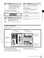
Page 51: ...th the device selection buttons to timeline setting mode h STOP button When pressed this lights amber and operation of the device selected with the device selection buttons stops i Search dial Use this for search and other operations on the material of an external device For details see Controlling Tape Disk Transport in Chapter 12 Volume 2 Keyframe Control Block In the keyframe control block you ...

Page 52: ...ting macro event is inserted after the current keyframe during macro editing macro event Pressing this button while holding down the SHIFT button inserts the deleted or copied keyframe during macro editing macro event before the current keyframe during macro editing macro event SHIFT Hold down this button and press the INS button MOD button or PASTE button to obtain the shifted function for the bu...

Page 53: ... NORM REV normal reverse Press this button turning it on to reverse the direction of the effect when it reaches the last keyframe or first keyframe Chapter 2 Menus and Control Panel Effect indicator d Duration setting buttons The following buttons are used to set the duration of a keyframe Fader lever Name Description KF DUR keyframe duration Press this button turning it on to set the keyframe dur...

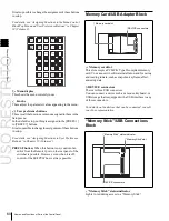
Page 54: ...with this button on it returns to the first keyframe and repeats k AUTO INS auto insert button When editing a macro press this button turning it on to enable the auto insert function so that every control panel operation you carry out is added to the macro as an event Numeric Keypad Control Block The numeric keypad control block is used for region selection for saving and recalling snapshots effec...

Page 55: ...ion attribute to a snapshot TRIM GPI ENBL enable After entering a difference value to be added to an existing setting press this button to confirm the change When the SNAPSHOT button is lit adds a GPI output attribute to the snapshot ENTER Confirm an entered value Name Description UNDO After recalling a register press this button to return to the state before recalling the register STORE STATS sto...

Page 56: ... video signal DME MON V is selected on the edit preview bus DME K DME monitor key When this button is pressed the DME monitor output key signal DME MON K is selected on the edit preview bus Chapter 2 Menus and Control Panel Fade to Black Control Block 3AUTObutton 1FTBbutton 2 Preview selection buttons a FTB fade to black button Press this button to fade to black the program output of the PGM PST b...

Page 57: ... the cross point buttons for shifted buses When the DME 1 V K to DME 8 V K buses are selected with the AUX delegation buttons the 1st row cross point buttons are for the currently showing side of DME and the 2nd row are for the reverse side By holding down the 2ND button and making an AUX delegation selection you can allocate the 2nd row to a different bus from the 1st row In this case if the 32nd...

Page 58: ...ecute an AUX mix transition on the 1st row 2ND AUX MIX If the bus assigned in the 2nd row is different from the bus assigned in the 1st row press this button turning it on to execute an AUX mix transition on the 2nd row Auxiliary Bus Control Block for Router Control Press the RTR button turning it on to assign the auxiliary bus control block to router control 3DESTbutton mLevelselectionbuttons kAu...

Page 59: ...green When the 32nd button is set as a SHIFT button in a 32 button system you can selectthe shifted sources in the 1st and 2nd rows Also by using the KEY button you can expand the source selection as follows See Using the Auxiliary Bus Control Block for Router Control Setting Button in Chapter 19 Volume 2 h 2ND button After selecting a destination with the destination selection buttons hold down t...

Page 60: ...ctions or menus assigned to themin the Setup menu In the default setup nothing is assigned to the PREFS 1 to PREFS 7 buttons Itisalsopossibletochangetheassignmentofthese buttons in setup For details see Assigning Functions to User Preference Buttons in Chapter 19 Volume 2 PREFS 8 button When this button is on control of an editor from the Remote1 port on the rear panel of the switcher is possible ...

Page 61: ...O Duo Notes When using a Memory Stick PRO high rate data transfer using parallel interface is not supported A MagicGate Memory Stick can also be used but this system does not support the MagicGate function When using a Memory Stick Duo be sure to use it cannot be removed resulting in a serious accident Handling Memory Sticks When using Memory Sticks pay attention to the following points Do not tou...

Page 62: ...he assigned macro and the button flashes yellow You can also assign enabling and disabling of macro attachment to use as the MCRO ATTCH ENBL button You can make a setup setting such that when the MCRO ATTCH ENBL button is On the buttons for which a macro attachment is set light Fordetails see AssigningaFunctionto aMemoryRecall Button in the Utility Shotbox Control Block in Chapter 19 Volume 2 Tran...

Page 63: ...ess any of the following buttons turning it on to select the transition type Press one of these buttons turning it on to determine the type of the next transition for a background To select the key transition type see page 95 hold down the KEY1 or KEY2 button and press one of the following buttons turning it on When multi program mode is selected in the Setup menu two or more of the following butt...

Page 64: ... buttons are used to save and recall a snapshot wipe snapshot and DME wipe snapshot Name Description WIPE When saving or recalling a wipe snapshot use this in combination with the buttons of the memory recall section DME When saving or recalling a DME wipe snapshot use this in combination with the buttons of the memory recall section SNAPSHOT When saving or recalling a snapshot use this in combina...

Page 65: ...y delegation for keys 1 to 8 to any buttons in this control block For details see Assigning Keys to the Independent Key Transition Control Block Simple Type in Chapter 19 Volume 2 3K SS button 4 Keysourcename display key snapshot buttons b Independentkeytransitionexecutionsection Thefollowingbuttonsareusedtocarryoutindependent key transition operations Name Description KEY3 ON This inserts or dele...

Page 66: ... rapid succession changes its state so that you can make cross point selections on the corresponding key bus b Independent key transition type selection buttons Press one of these buttons turning it on to select the downstream key transition type Name Description CUT Instantaneously insert or delete the key selected with the key delegation buttons SHIFT When setting is made in the Setup menu to al...

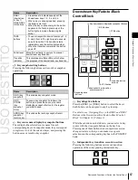
Page 67: ...y snapshot recall Chapter 2 Menus and Control Panel DownstreamKey Fade to Black Control Block 4 Key source name display key snapshot buttons 3K SSbutton 5FTBbutton d Key snapshot setting buttons Pressing the following buttons carries out key snapshot operations 7Previewselection buttons 6AUTObutton 2 Independent key transition executionsection 1Keydelegation buttons e Key source name display key s...

Page 68: ... signal DME MON V is selected on the edit preview bus DME K DME monitor key When this button is pressed the DME monitor output key signal DME MON K is selected on the edit preview bus Chapter 2 Menus and Control Panel g Previewselectionbuttons Press one of these buttons to select a signal on the edit preview bus Each of these buttons can be assigned to any key in setup For details see Assigning Pr...

Page 69: ...n selection buttons 7PRIORSETbutton 4 Wipe direction selection buttons 3 Transition execution section 8Independentkey transition execution section 5TRANSPVWbutton a Next transition selection buttons Pressthesebuttons turning themon todetermine whatthe next transition will apply to b Transition type selection buttons You can assign these buttons in setup to any transition type For details see Setti...

Page 70: ...menu Chapter 2 Menus and Control Panel c Transition execution section This section is used to carry out a transition and check the signal status during the transition Transition indicator Fader lever d Wipe direction selection buttons For details see Wipe direction selection buttons page 39 e TRANS PVW transition preview button When this button is lit you can check in advance the video changes dur...

Page 71: ...n Flexi Pad control block 2Transition control block compact type 3 Device control block trackball 4 MultifunctionFlexi Pad control block 1Cross point control block a Cross point control block For details of cross point control block operation see Cross Point Control Block page 32 For operations in AUX control mode see Auxiliary Bus Control Block for AUX Buses page 56 and Cross Point Control Block ...

Page 72: ...ifunction Flexi Pad control block For details of operations see Multifunction Flexi Pad Control Block page 73 Cross Point Control Block CCP 6224 6324 in AUX Operating Mode On the CCP6224 6324 by pressing the AUX CTRL buttononthe24 pointcross pointcontrolblock thebutton functions are changed to functions that select AUX buses and corresponding source signals AUX panel less function aAUXcontrolblock...

Page 73: ...Off On Key source signal names for AUX bus Chapter 2 Menus and Control Panel used as AUX bus cross point selection buttons with the source name display showing the source names or the bus names AUX panel less function AUX delegation buttons AUX cross point buttons For details of AUX mix transition operation see AUX Mix Transitions page 119 c AUX CTRL AUX control button This switches the cross poin...

Page 74: ... Menus and Control Panel 4 Alphanumeric display 1 Mode selection buttons 2 EDIT ENBL button 3 Region selection buttons 7 Adjustment knobs 5 Memory recall section 6Adjustmentknob displays a Mode selection buttons Pressing the following buttons selects the mode b EDIT ENBL edit enable button By pressing this turning it on you can carry out the following operations Effectcreation editing Snapshot att...

Page 75: ...or and use a mouse The menu operations using a mouse are basically the same as the menu control block operations described here with mouse clicks in place of button presses However since the monitor has no knobs for adjusting the parameters in the menu control block For details of operations corresponding to these knob operations see Operation With a Mouse page 85 d Alphanumeric display This shows...

Page 76: ...een page 77 Pressing a button other than a top menu button twice in rapid succession Depending on the button this may display a fixed page or the page selected last time you accessed the menu For details of the menus which can be recalled see Menus Accessed by Pressing a Button Twice page 399 Press the menu page selection button at the top left of the menu display The top menu window appears press...

Page 77: ... setup User setup settings Chapter 24 Volume 2 ENG SETUP Engineering Setup Setup functions Chapter 18 to Chapter 23 Volume 2 DIAG Diagnosis Status information display Chapter 25 Volume 2 Example of Displaying a Menu To display for example the M E 1 Key1 Type menu use either of the following operations Press the top menu selection button M E 1 then press the VF1 Key1 button and the HF1 Type button ...

Page 78: ...o Key4 and Key5 to Key8 button displays Switch the displays using the KEY1 4 and KEY5 8 menu title buttons When KEY1 4 is lit Key1 to Key4 buttons appear in VF1 to VF4 When KEY5 8 is lit Key5 to Key8 buttons appear in VF1 to VF4 b Menu page number button This shows the menu screen page number When you press this button the top menu window see page 80 appears You can enter the page number for the d...

Page 79: ...able the function to display a parameter group and adjust the parameters with the knobs or to execute the function These buttons are in groups by function In the screen example shown on the previous page the Key Bus and Matte function buttons constitute the Key Fill group g Parameter group button This displays parameter group names for which the knobs can make adjustments the current parameter set...

Page 80: ...nu window with the current menu remaining in the menu display If you enter a page number then press this button this confirms the value in the input display If it is a correct page number the top menu window closes and the menu display shows the new menu If it is not correctly set the input display changes color f Close button Press this to close the top menu window g Add Favorite button Pressingt...

Page 81: ...of frames per second 1 f minus button This toggles the sign of the entered value When it is pressed the value is negative g Clear button This clears the input It does not change the parameter setting a Item display This is the name of the parameter being set in the numeric keypad window b Max min maximum minimum value indication This shows the maximum and minimum settings of the parameter h Trim b...

Page 82: ...nter filenames in capital letters f Shift button This selects the characters onthe shiftside of the keys The shift is released when you enter a character g Space button This enters a space character h Clear button This clears all of the characters in the input string i Del button This clears the character immediately after the cursor in the input string j Left button This moves the cursor one char...

Page 83: ...r is used as the source for copying Next press a different color palette button to copy to that button Swap If you press two color palette buttons in sequence with this button held down the two colors are swapped Default If you press any color palette button with this button held down the color palette button is set to the default color c Color display This shows the setting color and the paramete...

Page 84: ...ample Chroma Adjust in the Type menu Setting Parameters mark The mark above on a function button indicates that there are parameters which can be adjusted with the knobs Pressing this function button assigns parameters to the knobs Youcan set the parameter values byeither of the following methods Turn the knob 1 to 5 corresponding to the parameter to adjust the value Press the knob parameter butto...

Page 85: ...k the mouse instead of pressing a button as described in the previous section Menu Operations However in the following cases there are special operations with a mouse To set a parameter with the mouse To adjust the value of a knob setting parameter button with the mouse you can use anyof the following three methods Position the cursor over the knob setting parameter button for which you want to ad...

Page 86: ...p Edit The following menu appears 3 With the cursor select the group name in this case a blank button for the operation 4 Press Rename A keyboard window appears 5 Enter a group name maximum 24 characters and press Enter This confirms the group name To copy a menu group 1 In the Home Favorites Group Edit menu press the button for the copy source group 2 Press Copy Customizing the Shortcut Menu Assi...

Page 87: ...ton settings Button name Menu No Notes The shortcut menu settings are handled as part of the control panel setup You can recall and save them in the same way as setup data To register a menu macro on a button See Recalling a Menu Macro Register and Executing a Menu Macro in Chapter 16 Volume 2 2 Move the cursor to the position where you want to displaythe button To changethe content of an already ...

Page 88: ...llowing illustration shows the flow of operations for carrying out a transition on an M E bank or the PGM PST bank Select current background video page 89 Select next transition page 95 Background Keys 1 to 8 Select new background video page 89 Make key settings page 123 Select transition type page 95 Cut Mix NAM Super mix Preset color mix Wipe DME wipe Make wipe settings page 163 Make DME wipe se...

Page 89: ... number The basis of signal selection is to select in a cross point button row the cross point button to which is assigned the desired signal Reentry buttons To use the output of one M E bank as the input signal to another bank use the reentry buttons M E 1 M E 2 and M E 3 on the auxiliary bus control block M E 1 M E 2 M E 3 and PGM in the cross point control block of the destination bank For exam...

Page 90: ... d Key 1 row Turn on the dedicated SHIFT button then turn on the KEY3 button Key 8 bus d Key 2 row Turn on the dedicated SHIFT button then turn on the KEY4 button PGM PST Program bus b Program row Preset bus b Preset row DSK 1 bus DSK 1 row Turn off the dedicated SHIFT button then turn off the DSK3 button c DSK 2 bus DSK 2 row Turn off the dedicated SHIFT button then turn off the DSK4 button c DSK...

Page 91: ...Key 1 source to M E 1 Key 8 source buses M E 2 Key 1 fill to M E 2 Key 8 fill buses M E 2 Key 1 source to M E 2 Key 8 source buses M E 3 Key 1 fill to M E 3 Key 8 fill buses M E 3 Key 1 source to M E 3 Key 8 source buses M E 4 Key 1 fill to M E 4 Key 8 fill buses M E 4 Key 1 source to M E 4 Key 8 source buses M E 5 Key 1 fill to Key 8 fill buses M E 5 Key 1 source to Key 8 source buses DSK 1 sourc...

Page 92: ... rows as the auxiliary bus control block This is called the panel less function Selecting the AUX bus 1 Switch the operation mode with the AUX CTRL button 2 In the key 1 row select the AUX bus for the operation 3 In the key 2 row select the desired signal Signal Assignment and Selection Assigning signals to buttons Each of the 32 cross point buttons and reentry buttons has a corresponding button n...

Page 93: ...the signals of button numbers 1 to 31 press the cross point button for the desired signal To select button numbers 32 to 62 hold down the shift button and press the cross point button for the desired signal Button numbers in the auxiliary bus control block 2ND button 1st row 2nd row When the 2ND button is unlit The cross point buttons and reentry buttons in the auxiliary bus control block have sep...

Page 94: ...taneously Selection of signals linked with the audio mixer When you select a signal in a switcher bank background A key 1 or key 2 row of the CCP 6224 6324 control panel in AUX control mode or AUX bus control block of the CCP 8000 and the bank and signal are set to be linked to the audio mixer then the program output of the audio mixer follows the signal selection For details of the setting see Ma...

Page 95: ...w video increases progressively to 100 then the current video is progressively reduced from 100 to zero in the second half with the new video maintained at 100 output Notes This transition type is not available for an independent key transition Super mix In this dissolve the current video is maintained at 100 output for the first half of the transition as the new video is mixed while increasing pr...

Page 96: ... the background video with the background A row of cross point buttons 2 Select the way in which the transition will affect the image usingthenexttransitionselection buttonsinthe transition control block For an overview see Selecting the Next Transition page 95 To change the background Press the BKGD button turning it on To insert or delete a key Press one of the KEY1 to KEY4 buttons or DSK1 to DS...

Page 97: ...required settings according to the selected transition type For details of the settings see the relevant section Super mix Super Mix Settings page 102 Preset color mix Color Matte Settings page 103 Wipe Basic Procedure for Wipe Settings page 163 DME wipe Basic Procedure for DME Wipe Settings page 187 Clip transition Clip Transition Operations page 219 Using the transition preview function see page...

Page 98: ... transition you can also change the key priority in the new video The key priority values go from 1 to 4 with a higher priority key being in front as seen on the screen Priority sequence on the screen There are two ways of setting the priority either using the PRIOR SET button in the transition control block or using the Misc menu to access the Key Priority menu for the M E or PGM PST bank Notes W...

Page 99: ...t is not possible to set a priority sequence of keys 1 5 and 2 The selected key now appears on top on the program monitor The priority of keys other than the selected one does not change Key priority 1 3 4 2 To change the priority of more than one key repeat this operation as required Changing the key priority for after the transition When executing a transition turning on the next transition sele...

Page 100: ...Priority menu appears 2 Foreachof Priority1 Priority2 Priority3 and Priority4 select a key to determine the keypriority sequence For details of the key priority sequence see the figure shown for step 2 in the previous item see page 100 The keys appear in the set order on the preview monitor 3 Execute the transition The keys are rearrangedin thesetorderontheprogram monitor 1 IntheM E orPGM PST menu...

Page 101: ...ample keystatus displaygiven when the KEY PRIOR button is pressed Current key priority 1 2 3 4 Key priority after the transition 3 2 1 4 Indicators 1 3 flashing 2 1 flashing 3 4 4 In Lower Group select the other group 5 Set the priority for the other group Lit Lit Flashing Flashing Lit Lit Example key status display showing the key priority after the transition Priority Setting for Keys 1 to 8 Set...

Page 102: ...d with the knobs according to the selected transition type For details see the following Super Mix Settings page 102 Color Matte Settings page 103 Setting the Transition Rate page 105 Notes When multi program mode is selected in the Setup menu there may be cases in which two or more transition types have been selected For details see Setting the Operation Mode in Chapter 20 Volume 2 Super Mix Sett...

Page 103: ...the background for the next transition One stroke mode and one time mode You can make a setting such that a preset color mix is carried out in a single transition This is called one stroke mode When the bus fixed mode is selected with a Setup menu setting a preset color mix is always carried out in the one stroke mode You can also make a setting such that when a preset color mix is completed the n...

Page 104: ...enu setting it is possible to preserve the key state while carrying out the color matte mix Setting the color matte 1 IntheM E orPGM PST menu selectfirstVF7 Misc then HF1 Transition The Transition menu appears 2 Select Preset Color Mix in the Transition Type group 3 In the Preset Color Mix Fill group select one of the following Flat Color monochrome color matte Utility 2 Bus signal selected on the...

Page 105: ... numeric keypad control block page 106 Frame input mode The entered value is a number of frames Example Entering 123 constitutes an entry of 123 frames Timecode input mode The entered value is a timecode value Example Entering 123 constitutes an entry of 1 second 23 frames Notes Whereas you can enter a value of up to 999 in frame input mode a value not smaller than 10 seconds cannot be entered in ...

Page 106: ...ing for the region 3 With the numeric keypad enter the transition rate If required press the TC button to toggle the input mode frame input or timecode input Enter a value of up to three digits Memory recall section Flexi Pad control block standard type 2 Enter the desired transition rate with the numeric keypad If required press the TC button to toggle the input mode frame input or timecode input...

Page 107: ...ck transition rate and change the settings see page 234 Pattern Limit 4 Press the TRNS button You can now set the M E 1 block background transition rate 5 Watching the alphanumeric display enter the transition rate you want to set with the memory recall section button If required press the TC button to switch the input mode frame count input or timecode input When a wipe or DME wipe pattern is sel...

Page 108: ...Edge Direction When a DME wipe is selected as the transition type in the M E or PGM PST menu select first VF6 DME Wipe then HF4 Edge Direction The Edge Direction menu appears 2 Press the Pattern Limit button turning it on 3 Turn the knobs to adjust the following parameters Knob Parameter Adjustment Setting values 1 Pattern Limit Pattern limit 0 00 a to 100 00 b a 0 00 Executing the transition does...

Page 109: ...ition rate 2 If you selected IndependTrans Rate in step 1 adjust the following parameter Fader lever CUT button AUTO TRANS button Transition control block standard type To execute a transition on the M E or PGM PST bank by a button operation use the following procedure in the transition control block To carry out an instantaneous cut transition Press the CUT button To carry out a gradual transitio...

Page 110: ... is in an intermediate position when a transition is completed as an auto transition then the lever position no longer agrees with the transition state This is termed a non sync state In a non sync state two lit LEDs indicate the position from which a normal transition can be carried out This is either at one end position or both end positions of the fader lever travel Moving the fader lever towar...

Page 111: ...n for example the fader lever position does not agree with the signal output this is a non sync state see page 110 and LEDs light at both end positions of the fader lever travel Moving the fader lever does not carry out a transition but when the fader lever reaches the end position the non sync state is released and it is now possible to carry out the next transition If the fader lever is moved in...

Page 112: ...check the effect of the transition To terminate a transition preview There are three modes for a transition preview To terminate a transition preview carry out the operation according to the mode and press the TRANS PVW button turning it off Lock Toggling the TRANS PVW button on and off switches between the transition preview mode and the normal mode Hold The preview mode obtains only while the TR...

Page 113: ...h a combination of transitions simultaneouslyon a keyas auto transitions see page 109 the result depends on the timing of pressing the respective AUTO TRANS buttons Simultaneous execution If the AUTO TRANS buttons for the two transitions are pressed simultaneously the following is the result Note that in both cases thecommon transitionisa wipeand the independent key transition is a mix dissolve De...

Page 114: ...y Example 1 Whenthe independent key transition AUTOTRANS button is pressed later Example When the independent key transition AUTO TRANS button is pressed later Common transition wipe Independent key transition mix Independent key transition mix The transition completes with the key deleted Common transition wipe Time offset execution with the key not inserted Thekeyisdeleted even if the independen...

Page 115: ...ard type To set independent transitions for the keyers on the M E or PGM PST bank use the independent key transition control block 1 Select one or more of the delegation buttons KEY1 to KEY4 DSK1 to DSK4 in the PGM PST bank turning them on You can press more than one button at the same time Notes The buttons for Key5 to Key8 and DSK5 to DSK8 require previous assignment in the Setup menu see page 3...

Page 116: ...s are set the effects may be applied during wipe transitions If the effects are not necessary cancel the settings Trail Motion Decay Wind When the Keyframe Strobe effect is set operating keyframes do the same effect Cancel the unnecessarysettings Independent key transition operations when using the CCP 6224 6324 Control Panel Independent key transition execution section Transition control block co...

Page 117: ...dent key transition rate in the numeric keypad control block Notes You cannot usethenumeric keypad controlblockto set the transition rate for a simple transition 1 In the numeric keypad control block hold down the TRANS RATE button and in the independent key transition control block press the delegation button KEY1 to KEY8 DSK1 to DSK8 in the PGM PST bank for the key for which you want to set the ...

Page 118: ...apshot button above the correspondingdelegationbuttonwhenthe K SS buttonis off Displaying the independent key transition rates in a menu and changing the settings For each of the M E and PGM PST banks you can also display the transition rate independent key transition rate and fade to black transition rate and change the settings see page 234 Fade to Black ThePGM PST block provides a fade to black...

Page 119: ...transitions cannot be executed in 3D mode Preparations for AUX mix transitions The following preparations are required Preparations Refer to Assign the two AUX buses used for the AUX mix to consecutive odd numbered and even numbered output connectors for example Output 1 and Output 2 Enabling AUX Mix Transitions in Chapter 20 Volume 2 Set the AUX mix transition rate page 235 Executing an AUX mix t...

Page 120: ...mage for after the transition Thisexecutesthetransitionatthepresettransitionrate The image during the transition is output from the AUX1 bus The image selected in step 4is output from the AUX2 bus Key transition selection buttons Key status display Transition type selection buttons Transitionexecutionsection Transition control block simple right hand type Notes The simple transition control block ...

Page 121: ...Color Matte Settings page 103 Wipe Basic Procedure for Wipe Settings page 163 DME Wipe Basic Procedure for DME Wipe Settings page 187 Clip transition Clip Transition Operations page 219 5 Carry out the transition in the transition execution section For a gradual transition such as a mix or wipe Press the TAKE button or operate the fader lever Display of the Key Output Status and Key Priority You c...

Page 122: ...E button turning it on To insert or delete a key using a dedicated DME wipe pattern Press the DME button turning it on For details of wipe settings see Wipe Settings for Independent Key Transitions page 175 For details of DME wipe settings see DME Wipe Settings for Independent Key Transitions page 193 To cut the key instantaneously in or out Press the CUT button turning it on If in the Setup menus...

Page 123: ...ing to the luminance Y of the key source signal and at the same time the key fill signal is cut out and then added to the background signal Linear key This is a type of luminance key but there is a reduced variability in gain allowing more precise adjustment Color vector key The key signal is created from a combination of the luminanceand chrominancecomponents of thekeysource signal When perfect k...

Page 124: ...Fine Key and zabton functions go off Soft edge This softens the edge of the key Zabton This inserts a translucent pattern behind a key You can adjust the pattern size softness density and color Chapter 4 Keys Chroma key A key signal based on a particular color is used to cut out the background and the key fill is then inserted The inserted signal is also referred to as the foreground and the compo...

Page 125: ...r the signal currently selected on the utility 1 bus In the case of an outline there is no edge fill signal selection because the key fill signal fills the outline and the rest of the image remains as the background For the emboss effect in place of the edge fill signal the emboss fill matte 1 and emboss fill matte 2 signals are used Masks A mask is used to inhibit the effect of a key over a part ...

Page 126: ...ning the key adjustment values to their defaults page 149 For the menu operation to return the key adjustment values to their defaults see Returning to Default State in Function Groupings page 85 Key Setting Operations Using Menus There are two ways of making key settings either using menus or using the key control block or the Multifunction Flexi Pad control block This section describes basic pro...

Page 127: ... key Color Vector color vector key Wipe Pattern wipe pattern key Key Wipe Pattern key wipe pattern key 3 Carry out the following settings as required depending on the key type selected in step 2 To enable clean mode see page 123 for a luminance key linear key or color vector key Select Clean Mode so that it is set on When clean mode is enabled key fill is added to the background without cutting ou...

Page 128: ...for use as key fill Key Bus signal selected on the key 1 fill bus Matte signal from the dedicated color matte generator 3 If you selected Key Bus in step 2 select the key fill signal on the key 1 row in the cross point control block For the CCP 6224 6324 Control Panel it is necessary to set the AUX CTRL button to Off in order to exit the AUX panel less function see page 92 4 If you selected Matte ...

Page 129: ...hapter 19 Volume 2 Setting the KEY button operating mode For details see Setting the Button Operation Mode in Chapter 19 Volume 2 Selecting key source and key fill in the menu Selecting key source For example to select the key source for M E 1 key 1 use the following procedure 1 In the Key Fill group of the M E 1 Key1 Type menu hold down Key Bus 2 Press Signal Select The Signal Select menu appears...

Page 130: ... following parameters 6 To interchange color 1 and color 2 press Color Invert turning it on Chroma Key Composition and Basic Settings In creating a chroma key image either a normal mix or an additive mix can be used To select which use the Type Chroma Adjust menu for the keyer Normal mix The foreground is cut out with the key signal andthen combinedwith thebackground which has also been cut out wi...

Page 131: ...ments as required The following manual adjustments are possible Key active When this function is off only the foreground is output andyou can make adjustments of color cancel see thenext paragraph Color cancel If the foreground image includes shades ofthe background color turn this function on to remove the color from the foreground image Chroma key window You can adjust the range over which the k...

Page 132: ...ey signal for the composition this produces the foreground with the color cancel effect applied This can therefore be used to provide an impression of smoke for example When the Y balance function is applied to the color cancel key the relevant part is output in its original color without canceling and therefore it is possible to combine colors which are the same color as the background i e typica...

Page 133: ...g Y Balance on and adjusting the Making key signal adjustments for color cancel When thecolor cancel function is set on you can adjust the key signal for color cancel 1 In the Color Cancel group of the Chroma Adjust menu set Color Cancel on 2 In the Color Cancel group set Cancel Key on The cancel key is now on and you can now adjust the key signal for color cancel Knob Parameter Adjustment Setting...

Page 134: ... Modifications To modify the key edge of key 1 on the M E 1 bank use the following procedure 1 In the M E 1 Key1 menu select HF2 Edge The Edge menu appears 2 Select the edge type see page 124 in the Edge group Normal unadorned edge Border edge with border applied Drop Border edge with drop border applied Shadow edge with shadow applied Outline edge used as outline Emboss embossing effect applied t...

Page 135: ...ange is 0 00 to 4 00 When emboss is selected For thecolormix operation see Carrying out acolor mix for the key edge fill matte page 136 6 When emboss is selected for the edge type adjust the To adjust matte 1 press Matte1 and to adjust matte 2 press Matte2 then adjust the following parameters Knob Parameter Adjustment Setting values 1 Luminance Luminance 0 00 to 100 00 2 Saturation Saturation 0 00...

Page 136: ...sing a wipe pattern generated by the dedicated pattern generator 1 In the Edge Fill group of the Edge menu select Matte then press Matte Adjust The edge fill Matte Adjust menu appears 2 In the Edge Matte group select Mix Color turning it on 3 Adjust the following parameters Knob Parameter Adjustment Setting values 1 Size Pattern size 0 00 to 100 00 2 Soft Softness of pattern edge 0 00 to 100 00 3 ...

Page 137: ...low you select Mask Pattern and Box for the main mask the Size parameter here cannot be adjusted Set Size in the Main Mask menu 3 To adjust the pattern and color press Zabton Adjust The Zabton Adjust menu appears 4 In the Zabton Pattern group select the pattern Key Wipe Use a key wipe You can change this pattern by pressing Pattern Select to open the menu for key wipe pattern selection Pattern Sel...

Page 138: ...endix page 357 To select the pattern display the Mask Ptn Select menu bypressing Mask Ptn Select in the Main Mask menu After selecting one of the patterns standard wipe patterns 1 to 24 displayed in the Mask Ptn Select menu you can adjust the following parameters 5 To invertthe black and whitesense ofthemask source press Mask Invert turning it on 6 When a pattern is selected as the mask source set...

Page 139: ... turning it on Applying a DME Effect to a Key Notes When the SDI interface is used to connect the DME DME effects includingDME wipes can beusedinonly one place for one M E bank When the dedicated interface is used to connect the DME the number of keys to which DME effects including DME wipes can be applied simultaneously for one M E bank varies as follows depending on the executionmodeoftheDMEwipe...

Page 140: ... channel 7 or channel 8 turn on the KEY4 button in the key 2 row then select the signal in the key 4 row DME utility 2 bus Using four DME channels on one keyer When using the DME dedicated interface proceed as follows Notes On the MVS 8000X when the signal format is 1080P this operation cannot be carried out On the MVS 7000X when the signal format is 1080P the above restriction also applies if usi...

Page 141: ... settings Press Default Recall at the lower left of the menu display For details of the initial status see Saving User Defined Settings in Chapter 18 Volume 2 For the menu operation to return the key state to that set in initial status see Returning to Default State in Function Groupings page 85 Blink Function With the blink function you can obtain the following effects Specifying the Key Output D...

Page 142: ...Processing You can adjust the luminance and hue of the selected key fill signal For example to apply video processing to the signal selected on the M E 1 bank key 1 fill bus use the following procedure 1 In the M E 1 Key1 menu select HF7 Video Process The Video Process menu appears 2 Press Video Process turning it on 3 Adjust the following parameters To return adjustment values to their defaults P...

Page 143: ...settings is pressed that is on you can set the parameters with the four knobs If there are more than four values to be assigned to theknobs the MORE button lights amber At this point press the MORE button which turns green to assign the fifth and subsequent parameters to the knobs so that the parameter settings can be made When the LUM or LIN button is lit green Knob Parameter Adjustment Setting v...

Page 144: ...the key fill bus select the SELF mode by pressing the AUTO SEL button and SPLIT button simultaneously so that both are off When chroma key is selected as the key type select the SELF mode Key Edge Modifications To apply a modification to the key edge see page 124 press one of the edge type selection buttons in the key control block BDR button border DROP BDR button drop border SHDW button shadow O...

Page 145: ... Setting the outline parameters When the OUTLINE button is lit green the parameter settings depend on the key type and whether the separate edge function is active To activate the separate edge function press Separate Edge setting it on in the Edge menu for the key Separate edge off Knob Parameter Adjustment Setting values 1 Width Outline width 0 to 8 a 0 to 100 b 4 Density Outline density 0 to 10...

Page 146: ... lit amber changing it to green then adjust the following parameters a The pattern is the same as a standard wipe See Wipe Pattern List page 357 Using the subsidiary mask In the key control block press the SUB MASK button turning it on The parameter settings depend on the mask source selected as Wipe or Utility 1 Bus in the Mask Source group of the Sub Mask menu for the key When wipe is selected K...

Page 147: ... link mode c 0 when the system signal format is 1080P and the DME input output signal format is set to dual link mode When combining DMEs connected via the dedicated interface and the SDI interface you can increase the number of keys to which DME effects are applied simultaneously requires a setting in setup For details see Setting DME and Switcher Interfaces in Chapter 20 Volume 2 Assigning a DME...

Page 148: ...ce menu Notes When using a second key in combination with a dedicated interface select the signal to be used on the AUX bus You can check the DME operating status in the Status menu see page 236 Assigning the DME output signal to a monitor signal 1 Holding down the output destination specification button MON in the key control block use the DME channel selection buttons to select the DME channel D...

Page 149: ...en an M E delegation button is held down holding down a key delegation button together returns the key settings to the initial status settings Mode selection buttons Adjustmentknobs For details of the initial status see Saving User Defined Settings in Chapter 18 Volume 2 Region selection buttons Memory recall section Adjustmentknob displays Notes Toselect M E4 or M E 5 a previous button assignment...

Page 150: ...reen page 143 Linear key When the LUM or LIN button is lit green page 143 Chroma key When the CRK button is lit green page 143 Key wipe pattern key When the PTN button is lit green page 143 Selecting the key source AUTO SEL button The signal assigned as a pair with the key fill bus signal for the key row button in the cross point control block is automatically selected SPLT button Select a differe...

Page 151: ...e 152 If you press this button at the same time as any of the KEY1 to KEY4 buttons you can switch the trackball and joystick to the resizer setting mode ROT X button Whenthisisset to On you canrotate the key around on the X axis ROT Y button When thisisset to On you canrotate the key around on the Y axis For the parameters adjustable with the adjustment knobs see step 4 in Setting rotation of the ...

Page 152: ...KEY ADJ button is held down holding down the button for the selected key together returns the key settings to the initial status settings For details of the initial status see Saving User Defined Settings in Chapter 18 Volume 2 Resizer Resizer allows you to apply DME like effects such as imageshrinking magnificationand movement rotation as well as change of the aspect ratio to the processed key Th...

Page 153: ...esizer menu press Resizer turning it on 2 Adjust the following parameters with the knobs Key control block operations for key shrinking magnification rotation and movement Parameter group 1 2 Delegationbuttons RESIZER button Adjustment knobs 4 a X is turned on in the Rotation group of the Rotation menu b Y is turned on in the Rotation group of the Rotation menu Parameter group 2 2 MORE button 1 Us...

Page 154: ...unctions to Key Control Block Buttons in Chapter 19 Volume 2 5 Turn the knobs to adjust the following parameters ROT button RSZR button Z ring LOC button When ROT X is lit When ROT Y is lit ASP button 1 Press the RSZR CTRL button turning it on 2 Press the delegation button to select the key 3 Press the RSZR button turning it on 4 To change the aspect ratio turn on the ASP button To shrink magnify ...

Page 155: ... For details of how to make this selection see Selecting the State After Powering On Start Up Menu in Chapter 18 Volume 2 Resizer Interpolation Settings For example to make the interpolation settings for key 1 of the M E 1 bank use the following procedure 1 In the M E 1 Key1 Processed Key Resizer menu press Resizer turning it on 2 Press Resizer Process The Resizer Process menu appears 3 In the Vid...

Page 156: ... borders 0 00 to 100 00 HD format To apply color to a border 1 In the Border Mode group of the Border Crop menu press Flat Color 2 Adjust the following parameters To soften the inner edge of a border 1 In the Border Crop menu press Border Soft 2 Adjust the following parameters To apply a beveled light edge 1 In the Border Mode group of the Border Crop menu press Beveled Light Edge 2 Adjust the fol...

Page 157: ...a drop shadow 1 In the M E 1 Key1 Processed Key Resizer Enhanced Effect menu press Dual Rszr Effect turning it on 2 Press Drop Shadow turning it on 3 Set the parameters The validrangesoftheparametervaluesdependonthe combination of signal format SD HD and aspect ratio 4 3 16 9 selected in the system as follows SD format Knob Parameter Adjustment Setting values 1 H Horizontal position of shadow 8 00...

Page 158: ...ocessed Key Resizer Enhanced Effect menu press Defocus turning it on 2 Set the parameters This operation is the same as the defocusing setting when using the DME with the DME dedicated interface see page 303 Applying a mask to mosaic or defocus 1 In the M E 1 Key1 Processed Key Resizer Enhanced Effect menu press Dual Rszr Effect turning it on 2 Press Mask turning it on This enables the mask functi...

Page 159: ...ive Change perspective 0 0000 to 99 9999 Canceling Virtual Images If an extreme degree of perspective is set for an image the part of the image exceeding the virtual view point is displayed wrapped around on the monitor screen You can press Wrap Around turning it on to make a setting not to show the virtual images Setting rotation of the resizer Notes Either X or Y direction must be specified for ...

Page 160: ...napshot buttons Key snapshot setting buttons Recalling a key snapshot For example the following procedure recalls the state of the M E 1 key 1 settings 1 In the M E 1 independent keytransition control block press the key delegation button KEY1 turning it on 2 Press the K SS button turning it on 3 Set the following buttons on or off depending on the information you want to recall These buttons are ...

Page 161: ... the AUTO TRNS button Instant key insertion removal Press the KEY ON button To remove the key while the key is inserted press the KEY ON button Key Snapshot Operations Using a Simple Transition Module 2 In the memory recall section hold down the STOR button and press the button any of 1 to 4 for the register in which you want to save the key snapshot To recall a key snapshot For example to recall ...

Page 162: ... registers 3 and 4 The button you pressed lights yellow and this recalls the key settings excluding the key insertion state on off and key priority Independent key transition control block simple type Saving a key snapshot For example to save the settings of M E 1 key 3 use the following procedure 1 In the M E 1 independent keytransition control block press the K SS button in the key 3 control blo...

Page 163: ...pe patterns can be used for an independent key transition For wipe patterns see Wipe Pattern List in Appendix page 357 Standard wipe patterns Patterns consisting of straight lines vertically horizontally or diagonally and circular patterns Enhanced wipes More complex shapes such as hearts stars and round corners Rotary wipes These patterns involve rotation of the image about a point Mosaic wipe pa...

Page 164: ... the screen at 100 00 from the bottom or right edge of the screen b At 100 00 all rows appear simultaneously at 100 00 until one row of tiles is completely displayed the next row does not start to appear When a random wipe is selected pattern number 273 Knob Parameter Adjustment Setting values 1 H Size Tile width 0 00 to 100 00 2 V Size Tile height 0 00 to 100 00 3 Volatility Rate of tile generati...

Page 165: ...SEMI LINK semi linked mode 3 4 5 6 Start value End value 1 Mix combination of main and sub patterns already begun 2 Mix ends during transition which ends with sub pattern at 100 3 Beginswithmainpatternat100 4Endswithsubpatternat100 5Mixbeginsaftertransitionstarts 6Transitionendswithmainandsubpatternsstillinmix combination Parameter settings Start Point in the course of the transition at which the ...

Page 166: ...ix 1 In the Pattern Mix menu press Dust Mix turning it on 2 Set the following parameters as required Knob Parameter Adjustment Setting values 1 Mix Ratio Proportion of diamond dust pattern in mix 0 00 to 100 00 2 H Size Particle width 0 00 to 100 00 3 V Size Particle height 0 00 to 100 00 4 Flash Rate Rate of generation of particles 0 00 to 100 00 You can also apply the dust mix function to the pa...

Page 167: ... direction Normal Reverse alternate between regular and reverse for each transition Reverse reverse direction to normal To specify the wipe direction with a button in the transition control block In the transition control block of each of the M E 1 to M E 3 and PGM PST banks press the following direction selection buttons NORM Normal NORM REV Normal reverse REV Reverse Splitting the wipe pattern S...

Page 168: ...color combination in the Edge Matte group Flat Color Adjust color 1 with the following parameters Knob Parameter Adjustment Setting values 2 Saturation Saturation 0 00 to 100 00 3 Hue Hue 359 99 to 0 00 When you select Mix Color for a two color combination see the next paragraph Carrying out a color mix for the edge fill matte When you selected Matte for the border or soft border edge fill you can...

Page 169: ...Hue Hue 359 99 to 0 00 7 To interchange color 1 and color 2 press Color Invert turning it on Setting the wipe position Positioner When you turn on this function you can move the wipe pattern to any position Positioner Off Positioner On a See page 171 When turning Aspect on and setting the aspect ratio of the pattern a See page 171 When turning Angle on in the Rotation group and slanting the patter...

Page 170: ...ries out a wipe with the pattern in a fixed angle Angle Off Angle On The parameter Angle determines the angle of pattern rotation A value of 100 00 of the parameter Angle corresponds to one whole turn counterclockwise A value of 100 00 corresponds to one whole turn clockwise With a value of 0 00 there is no rotation Speed Through the course of the transition the wipe pattern rotates at a fixed spe...

Page 171: ...Magnitude is selected Setting the wipe pattern aspect ratio Aspect ratio You can freely change the aspect ratio of the pattern Multi Off Multi On The parameterH Multi determinesthe numberof pattern replications horizontally and the parameter V Multi determines the number of pattern replications vertically The parameter Shift determines the manner of At a value of 100 00 the pattern of the adjacent...

Page 172: ...etian blind Pairing Off Pairing On The parameter Width determines the width of the slits The parameter H Offset determines the spacing in the horizontal direction If a negative value is set the even numbered pairs of strip and slit move to the left and the odd numbered pairs move to the right The value 100 00 represents the maximum movement Ifa positive valueisset theeven numbered pairsofstrip and...

Page 173: ...um clockwise speed You can apply modulation independently to the main pattern and sub pattern 1 In the M E 1 Wipe menu select HF5 Main Modify The Main Modify menu appears 2 Depending on the desired effect in the Modulation group select one of the following H Horizontal modulation Modulate the pattern applying waviness in the horizontal direction to edges V Vertical modulation Modulate the pattern ...

Page 174: ... M E 1 Wipe menu select HF5 Main Modify The Main Modify menu appears 2 Press Spiral turning it on 3 Set the following parameters Knob Parameter Adjustment Setting values 1 Magnitude Size and direction of the spiral 100 00 to 100 00 2 Wave Speed Speed of the lateral waves 100 00 to 100 00 Possible combinations of wipe patterns and modifiers a Not patterns 1 to 16 19 and 20 b Not patterns 300 to 303...

Page 175: ... displays the M E 1 Key1 Transition WipeAdjust menu referredtobelow as the Key1 Wipe Adjust menu Selecting the independent key transition wipe pattern You select the independent key wipe pattern from the list of patterns displayed in the menu Notes In an independent key transition you can only use the standard wipe patterns pattern numbers 1 to 24 To select a wipe pattern for independent key1 on t...

Page 176: ...B1 K2 CB2 K3 or K4 to select one of keys 5 to 8 However it is not possible to select more than one key For details of assignment for keys 5 to 8 see Assigning Buttons for Selection of Keys 5 to 8 in the Setup Menu in the Appendix page 397 3 Press the POS button turning Position on 4 Movethe trackball or joystick to set the wipeposition By pressing the X button turning it on you can restrict moveme...

Page 177: ...eter You cansnapshotand saveawipepattern together withthe current settings of its modifiers and pattern limit in a dedicated register for recall when required There are 10 wipe snapshot registers on each M E bank and the PGM PST bank Use the Flexi Pad control block the Multifunction Flexi Pad block in each switcher bank or the Menu control block to save and recall wipe snapshots For simple transit...

Page 178: ... use the following procedure It is not possible to select a wipe pattern with a simple type Flexi Pad control block Canceling the saving of a wipe snapshot To cancel the saving of a wipe snapshot immediately after performing it hold down the STORE STATS button and press the UNDO button The STORE STATS button changes from amber to green Notes On a simple type Flexi Pad control block it is not possi...

Page 179: ...ot Operations With the Menus Menus used As an example when operating on M E 1 select M E 1 Wipe Wipe Snapshot The Wipe Snapshot menu appears lights amber In the upper left is shown the currently recalled register name or number Notes The Flexi Pad control block and menu settings are linked A setting in setup determines whether register names or pattern numbers appear Deleting a wipe snapshot from ...

Page 180: ...to wipe snapshot mode Editing the Wipe Pattern By pressing the EDIT ENBL button to switch the memory recall section to editing mode as shown in the following illustration you can edit the selected wipe pattern with the following buttons To exit from the editing mode press the EDIT ENBL button once more or press the EXIT button Region selection buttons Memory recall section You can change the indic...

Page 181: ... POS button the alphanumeric displayfirst shows the name of the parameter H or V and then the value of the parameter When the POS button is lit green you can adjust the position of the wipe pattern with the control knobs Buttons for setting the wipe direction NORM normal Sets wipe to normal forward direction NORM REV normal reverse Sets the wipe direction to alternate between normal and reverse fo...

Page 182: ... registers in which wipe snapshots are already saved light orange Canceling a saved wipe snapshot Immediately after saving hold down the STOR STAT button and press the UNDO button Buttons for registers in which a wipe snapshot is saved are lit orange Canceling recall of a wipe snapshot To cancel the operation of recalling a wipe snapshot press the UNDO button Deleting the data of a saved wipe snap...

Page 183: ...rethreeDMEwipeexecution modes dependingon the number of DME channels available one channel mode two channel mode and three channel mode The pattern numbers that can be used in these modes are as follows 8000A There is no such restriction for the MKS 7470X 7471X DME wipe pattern groups The patterns used in DME wipes fall into the following groups For each group excluding user programmable DMEs for ...

Page 184: ...o 1313 2701 to 2713 appears behind it 1315 to 1318 2715 to 2718 1341 to 1345 2741 to 2745 Page roll The new video unrolls like a scroll over the old video This is 1321 to 1333 2721 to 2733 a type of page turn 1335 to 1338 2735 to 2738 1346 to 1350 2746 to 2750 Frame in out Completed in two transitions In the first transition the new video appears then on the second transition the new video goes ou...

Page 185: ...901 to 1999 2901 to 2999 3901 to 3999 Notes In an independent key transition the following patterns can be used Execution mode DME wipe patterns that can be used One channel mode Slide split squeeze door 2D trans 3D trans frame in out page turn page roll mirror sphere character trail wave ripple split slide sparkle user programmable DME Two channel mode Page turn page roll DME Wipe Pattern Variati...

Page 186: ...set the Release Transition as follows Last 30 Last 5 Off Notes When pattern numbers 1701 and 1702 are selected crop cannot be used Relation Between DME Wipes and Other Effects The relations between DME wipes and other effects are as follows Relation to ordinary wipes DME wipes do not use the wipe generator built into the switcher Therefore during the execution of a DME wipe you can still use a pat...

Page 187: ...Settings for Independent Key Transitions page 193 For details of resizer DME wipe see Resizer DME Wipe Setting page 195 DME Wipe Settings Menu MVS 7000X Accessing the DME Wipe menu To access the M E 1 DME Wipe menu use either of the following operations In the menu control block select the top menu selection To select M E 4 or M E 5 a previous button assignmentin theSetup menuisrequired seepage396...

Page 188: ...ge of the screen b The vertical center position of the video pasted on Side V At 100 00 the center is at the bottom edge of the screen and at 100 00 the center is at the top edge of the screen When Frame in out for two channels is selected Pattern numbers 2851 to 2854 Knob Parameter Adjustment Setting values 5 Delay Timing for video selected on a utility bus to appear on the screen 100 00 to 100 0...

Page 189: ...Normal regular direction Normal Reverse alternate between regular and reverse for each transition Reverse reverse direction to normal To specify the DME wipe direction with a button in the transition control block In the transition control block of each of the M E 1 to M E 3 and PGM PST banks press the following direction selection buttons NORM Normal NORM REV Normal Reverse REV Reverse Modifying ...

Page 190: ...ode proceed as follows In one channel mode press 1st Ch turning it on In two channel mode from the Ch Select group select the corresponding channel You can select more than one channel at the same time 4 To move the position of the DME wipe pattern press the button where you want to move to turning it on The DME wipe pattern displayed on the screen moves to the position of the specified button Set...

Page 191: ... Left value shown Parameter group 2 2 Parameter group 2 2 Knob Parameter Adjustment Setting values 4 Bottom Crop the bottom of the image 100 00 to 100 00 Display indications when multiple channels are selected at the same time The indications on the knobs show the settings of the lowest numbered channel Whenyouturnthe knobsto adjust the settings this changes the settings on the other channels by t...

Page 192: ...ion group selectthe timing of transition completion Last 30 The transition completes at the end of 70 of the transition execution time The transition has a dead zone from 70 to 95 of the transition time Last 5 The transition completes at the end of 95 of the transition execution time When the transition completes the cropping is removed during the last 5 enlarges Off The transition completes at th...

Page 193: ...u referred to below as the Key1 DME Wipe Adjust menu 1 In the Pattern Select group of the Key1 DME Wipe Adjust menu press 1ch for one channel mode or 2ch for two channel mode The Pattern Select menu appears 2 SelectthedesiredDME wipepattern groupwithoneof the following buttons In two channel mode only Page Turn and Page Roll are selectable Slide Squeeze slide and squeeze Split Door split and door ...

Page 194: ...In the Crop Mode group press Crop or 4 3 Crop to crop to 4 3 in 16 9 mode turning it on 3 In the Crop Mode group press Remove From Begin The Remove From Begin menu appears For subsequent operations see step 5 of To set the action when a DME wipe crop transition is executed page 191 To set the timing of transition completion 1 In the Crop Mode group of the Key1 DME Wipe Adjust menu press Crop turni...

Page 195: ...le to select a resizer DME wipe for a key with processed key enabled Relation to resizer It is not possible to use a resizer DME wipe for a key with resizer enabled It is not possible to use a resizer DME wipe for a key forming a pair with a key with the dual resizer effect enabled The key combinations forming pairs are keys 1 and 2 keys 3 and 4 key 5 and key 6 and key 7 and key 8 For example when...

Page 196: ...s for wipe snapshot operations In DME wipe snapshot operations use the DME button instead of the WIPE button used in wipe snapshot operations Selecting a DME wipe pattern in the Flexi Pad control block In the standard type Flexi Pad control block enter a four digit pattern number using the DME button see page 178 Notes You cannot select aDMEwipe pattern in the simple type Flexi Pad control block A...

Page 197: ...lide Flip Tumble Flip Tumble Mosaic Defocus Frame in out Frame in out Frame in out H a Frame in out Frame in out V Frame in out Picture in picture b Picture in picture Compress c Picture in picture Two channel mode Dual transition mode Slide Squeeze 3D Trans Two channel frame in out Frame in out Two channel picture in picture Picture in picture a Transition according to DME wipe patterns 1202 1203...

Page 198: ...in picture one channel mode Create a minimum of three keyframes Either create the first keyframe image outside the screen area or set the image size to zero so that it cannot be seen within the screen Create the first transition to end such that the image can be seen within the screen At this point press the PAUSE button in the keyframe control block turning it on to set a pause for the keyframe E...

Page 199: ...y settings at a keyframe point at which the two images are not overlapping During the course of a transition there is a dead zone corresponding to the intermediate point of the whole effect see following figure during which the image does not change Therefore it is necessary to create the effect so that the image in the intermediate part of the transition is the keyframe for the mid point of the w...

Page 200: ...for DME wipe patterns have four digits see page 361 Editing the DME Wipe Pattern By pressing the EDIT ENBL button to switch the memory recall section to editing mode as shown in the following illustration you can edit the selected DME wipe pattern with the following buttons To exit from the editing mode press the EDIT ENBL button once more or press the EXIT button Notethat theoperation of thefollo...

Page 201: ...tern position to the center When you press the POS button the alphanumeric displayfirst shows the name of the parameter H or V and then the value of the parameter When the POS button is lit green you can adjust the position of the pattern with the control knobs Button for specifying effect size SIZE Specifies the effect size When the SIZE button is lit green you can specify the effect size with th...

Page 202: ...data SD system Without ancillary data Video format Memory capacity 480i 59 94 Approx 5600 frames 576i 50 Approx 4800 frames With ancillary data Video format Memory capacity 480i 59 94 Approx 4700 frames 576i 50 Approx 3900 frames For details of operating procedures see Still Image Operations page 204 Types of image and terminology used The following types of image are handled in frame memory Freez...

Page 203: ...ermed a pair file A pair file can be created by setting pair mode and capturing an image or by using the coupling function see page 221 to combine two single files A file other than a pair file is termed a single file A single file can be created by switching off pair mode and capturing an image or by using the separation function see page 221 to split a pair file Operation modes The frame memory ...

Page 204: ...ss point buttons To output a frame memory image to a monitor for example the output signal from the frame memory FM1 to FM8 must be allocated to a cross point button Carry out this allocation in the Setup menu Notes When the signal format is 1080P only the four options of FM1 to FM4 can be used Accessing the Frame Memory menu Most frame memory operations are carried out using the Frame Memory menu...

Page 205: ...mage capacity This shows the remaining number of frames When no more frames can be stored inpair mode 1 or 0 appears in red and in single mode 0 appears in red The lower figure shows the remaining number of frames that can be used as extended clips c Target FM selection buttons Display of ancillary data Extended clip display Status display Notes When the signal format is 1080P each time a still im...

Page 206: ...e is output Freeze when a freeze is output Record when continuously capturing images record e Pair button Press this button turning it on to enable pair mode f File selection area You can select from the displayed still image files or clip files File information detail display Selected file When a pair file is selected each press switches the front and the back Thumbnailindications Still image fil...

Page 207: ...o select both FM1 and FM2 Selecting a frame memory folder Press a button in the frame memory folder selection area see page 206 By pressing More to switch the display you can select from a maximum of 12 folders Thumbnails of the files within the selected folder appear source signals to which a DME effect is applied are assigned Capturing and Saving an Input Image Selecting Outputs and Target Frame...

Page 208: ...re saved automatically when the frame memory selection is changed For the following signal formats a field freeze is not possible 1080P 50 1080P 59 94 1080PsF 23 976 1080PsF 24 1080PsF 25 1080PsF 29 97 720P 50 720P 59 94 Saving a freeze image Store You can save an image in temporary memory which has been placed with the freeze function as a file in memory You can save a single image in a single fi...

Page 209: ...r frame memorysourcebus 2 remain return the frame memory source bus 2 settings to their default values When setting video processforthe framememorysourcebus2 disable the pair setting Setting a mask Masks can be set separately for frame memory source buses 1 and 2 To apply a mask to the signal selected on frame memory source bus 1 for example use the following procedure in the Still Freeze Store me...

Page 210: ...el increments and for each pixel moved the color is inverted Notes It is not possible to save an image moved with the reposition function directly to frame memory 1 In the Frame Memory menu select VF3 Reposition Lock and HF1 Reposition The Reposition menu appears In this menu you can also enable the V K mode see page 208 2 In the frame memory selection area select the FM output see page 207 3 In t...

Page 211: ...rea to select the folder to hold the freeze image see page 207 Notes The folder selected here is the destination folder for writing the freeze image It is not possible to change the selection of this folder after the following step 5 An orange bar appears on the selection button for the destination folder 5 Press Record Enable turning it on The signals of frame memory source buses 1 and 2 are assi...

Page 212: ...select the frame memory to be assigned see page 207 3 Select the desired folder in the folder selection area By pressing More to switch the display you can select from a maximum of 12 folders Thumbnails of the files within the selected folder appear 4 Turn the knob to select the register number in the user region Notes To search for an empty register in the user region use the numeric keypad contr...

Page 213: ... set to save with ancillary data For details see Saving a Frame Memory Clip With Ancillary Data in Chapter 18 Volume 2 Notes With this setting the saving mode for still images also changes to save with ancillary data but when playing back a still image the ancillary data is never played When you change thesaving mode theframe memoryis initialized and any existing recorded frame memory data is lost...

Page 214: ...ame Memory Clip Operations Notes During playback of a frame memory clip of the pair assigned to either of the target FM selection buttons see page 215 frame memory operations may not be performed properly Carry out frame memory operations after stopping clip playback Preparations for Operation Thepreparations forusing aframe memoryclip hereafter a clip are the same as for a still image operation F...

Page 215: ...e frame memoryselection area select an assigned target FM see page 207 3 If Direct Recall is on press the button turning it off 4 In the frame memory folder selection area select the desired folder By pressing More to switch the displays you can select from a maximum of 12 folders 5 Using the arrow keys or turning the knob scroll the file thumbnail display Knob Parameter Adjustment Setting values ...

Page 216: ...TOP or any of the SHTL JOG CUE REW FF and ALL STOP buttons For details of the buttons in the device control block search dial see Device Control Block Search Dial page 49 To specify the playback start point To make the current position the playback start point press the START TC button To set a different position press the SET START TC button then enter the timecode from the numeric keypad control...

Page 217: ...tion angle of the Z ring or amount of movement of the joystick When you pressed the VAR button Playback is at a speed corresponding to the rotation angle of the Z ring or amount of movement of the joystick in the range 1 to 3 times normal speed Clip Creation You save a movie as a clip Notes If the number of frame memory clips exceed 100 single files 50 pair files an error appears Using the menu to...

Page 218: ...n select No Notes It is not possible to delete the default folder named Default Clip Output As for still image operation you can use the reposition and lock functions For details of the operation see Image Output page 210 Recording and Playback of Ancillary Data Preparations To record ancillary data it is first necessary in the Setup menu to select save with ancillary data as the frame memory savi...

Page 219: ...Clip Transition Operations A frame memory clip movie is played back linked to a transition using a mix dissolve or wipe The following restrictions apply to the use of a clip transition Key frame capture is not possible It is not possible to apply a pattern limit Transitions executed in two strokes such as a preset color mix with the stroke mode set to Normal or a DME wipe with a picture in picture...

Page 220: ...ence axis see following figure is the position of frame 0 8 Using either of the following methods set the end point of the background transition Move the fader lever to the desired position and in the BKGD Transition Set Timing group press Stop Turn knob 2 to set the number of frames 9 If Wipe or DME Wipe is selected in the BKGD Transition Type group in the BKGD Transition Direction group select t...

Page 221: ...separate a pair file into two single still image files or clip files Creating a pair file from two single files Splitting a pair file into two single files Notes Carrying out the following operation automatically switches Pair to Off The following description applies to the case of FM1and FM2 but the procedures are similar for the other cases 1 In the Frame Memory Still Recall menu or Frame Memory...

Page 222: ...ame memory clip through the thumbnail display 5 Press Delete A message for confirming the deletion appears 6 To confirm the deletion press Yes and to cancel press No Knob Parameter Adjustment Setting values 1 No File selection 1 to maximum value 3 If necessary turn the knob check the contents of the frame memory clip through the thumbnail display Knob Parameter Adjustment Setting values 3 Viewer F...

Page 223: ...cher on which to carry out formatting file saving and file recall operations For details of Dual Simul mode see Selecting the System Operation Mode in Chapter 20 Volume 2 1 In the Frame Memory menu select VF6 External Device and HF1 Format or HF2 Backup Restore The Format menu or Backup Restore menu appears 2 In the region selection area see page 79 press SWR A popup window for selecting the switc...

Page 224: ...it A progress bar and numerical indication appear to show the progress of the operation When the operation is completed a popup window reading Completed appears 5 Press OK To rename a directory Select a directory in the list and in the button area press Rename In the keyboard window that appears enter the new directory name and press Enter The name of a directory is limited to eight characters Rec...

Page 225: ... VF6 External Device and HF4 Backup to DDR VTR The Backup to DDR VTR menu appears 2 To save with ancillary data output the frame memory output signal to the AUX bus 3 In the Backup Enable group select either of the following Clip Still Data from the first board still images and clips Ext Clip Data from the second board extended clips 4 Press Backup Start The message Preparing now is displayed in a...

Page 226: ...age are recorded single files V video Red red marker frame a Video tape Result of extraction Each section surrounded byred marker frames is extracted as a clip main file If the red markers surround a single frame then it is extracted as a still image In the case above two clip files main files are extracted and one still image file In the case above one clip file pair file is extracted a A red mar...

Page 227: ...USO RESTRITO Managing Images Using a DDR VTR 227 Chapter 7 Frame Memory Knob Parameter Adjustment Setting values 1 No File number 1 to maximum 3 Viewer Timecode for selected image 00 00 00 to maximum ...

Page 228: ...lor Bkgd1 menu Use either of the following operations In the menu control block select the top menu selection button COLOR BKGD and press VF1 Color Bkgd1 Press a cross point button assigned to color background 1 twice in rapid succession Basic Color Background Setting Operations Making a single color matte Flat Color If you are not using the color mix function to combine two colors use the followi...

Page 229: ...1 to 4 a a See page 171 When turning Aspect on and setting the aspect ratio of the pattern Knob Parameter Adjustment Setting values 1 Aspect Aspect ratio 100 00 to 100 00 a a See page 171 When turning Pairing on and making a wipe pattern like a Venetian blind When turning Angle on in the Rotation group and slanting the pattern Knob Parameter Adjustment Setting values 1 Angle Angle of pattern rotat...

Page 230: ...e done with a menu operation M E copy and M E swap You can copy and swap the overall bank settings among the M E 1 to M E 5 and PGM PST banks Notes If a DME is being used on the source M E bank then if for example there are insufficient DME channels it may not be possible to select the DME There are no such restrictions on a swap Keyer copy and keyer swap You can carry out copy and swap operations...

Page 231: ...000X M E 5 PGM PST Downstream keys 1 to 8 Matte data copy and swap You can copy or swap the matte data among the color generators listed in the following table DME channel copy and swap You can copy and swap the channel data among DME channels 1 to 4 or DME channels 5 to 8 It is not possible to copy or swap the channel data between DME channels 1 to 4 and DME channels 5 to 8 Notes On the MVS 8000X...

Page 232: ...copy press Copy and to swap press Swap To undo a copy or swap Press Undo to return to the state before the copy or swap was carried out Copy by Button Operation You can carry out the following copy operations by a simple button operation M E copy Keyer copy Wipe copy DME wipe copy Notes On the CCP 6224 6324 it is not possible to carry out a copy by button operation Basic button operation The basic...

Page 233: ...witcher Remote1 to Remote4 ports RS 422A D sub 9 pin Switcher GPI port parallel 25 pin DME1 DME2 Editor ports RS 422A D sub 9 pin DME1 DME2 GPI ports parallel 25 pin When the signal format is 1080P you can also make settings for DME3 DME4 2 In the Switcher or DME group press on the name of the port for which you want to disable control from an external device turning it off To re enable control fo...

Page 234: ...l Input Settings Input Menu and Signal Output Settings Output Menu in Chapter 20 Volume 2 3 Press Safe Title to set it on or off Displaying a List of Transition Rates and Changing the Settings In the Misc Transition Key ME FTB menu for each bank you can display a list of the M E or PGM PST transition rates and independent key or DSK transition rates and change the settings These settings are linke...

Page 235: ...s 2 Key2Trans Rate Key 2 transition rate 0 to 999 frames 3 Key3Trans Rate Key 3 transition rate 0 to 999 frames 4 Key4Trans Rate Key 4 transition rate 0 to 999 frames To set the fade to black transition rate in the Transition Key ME FTB menu 1 In the Misc Transition Key ME FTB menu press FTB 2 Turn the knob to set the number of frames Press the arrow keys to scroll the reverse video cursor Turn th...

Page 236: ...he reverse video cursor Turn the knob to make the setting a When AUX mix transitions are enabled even numbered buses cannot be selected as the target 2 Press Video Process turning it on 3 Adjust the following parameters Status Menu The Status menu shows the following information Operating status of the DME Viewing the DME operating status To view the DME operating status press the top menu selecti...

Page 237: ...shows the levelassignment status to the Level 1 to Level 4 buttons Selecting the level In the Level Button No group at the lower right in the above illustration press the selected level for switching For details see Using the Auxiliary Bus Control Block for Router Control in Chapter 19 Volume 2 1 Press Change Xpt The Router Router Control Router Control Change Xpt menu appears Destination Select b...

Page 238: ...adjustments apply For each of the following buses you can switch video process adjustments on or off and adjust the parameters Following buses in the M E 1 to M E 5 and PGM PST banks Key fill buses for keys 1 to 8 Background A and background B buses Utility 1 and utility 2 buses Frame memory source 1 and frame memory source 2 buses Aux 1 to 48 buses These settings also apply to keyframes and snaps...

Page 239: ... the M E 1 bank For the background B bus or utility bus 1 or 2 make the adjustment with a similar procedure Making video process settings for each bus 1 In the menu control block press the top menu selection button M E 1 and select VF7 Misc and HF2 Video Process 2 In the Bkgd A group press Video Process turning it on 3 Adjust the following parameters Knob Parameter Adjustment Setting values 1 Vide...

Page 240: ... corrector enables video signal color correction black balance white balance adjustment gamma correction knee correction etc Restrictions on color corrector and M E combination Notes To use the color corrector the BZS 8420X for MVS 8000X or the BZS 7420X for MVS 7000X Color Corrector Software is required To use the software you are required to input an install key For the method of inputting an in...

Page 241: ...lecting the color corrector output signal By assigning the signal output from the color corrector to a cross point button you can make that signal available on that button For details of the assignment process see Cross Point Settings Xpt Assign Menu in Chapter 19 Volume 2 Accessing the CCR menu For color correction operations use the CCR menu To access the CCR menu in the menu control block press...

Page 242: ... Overall gain adjustment of the video signal Gain adjustment of the Y signal Gain adjustment of the C signal Hue delay Black level adjustment To apply input video processing effects use the following procedure 1 In the CCR menu press VF1 CCR1 and HF1 Input Process The Input Process menu appears 2 In the Input Process group press Input Process turning it on 3 Adjust the following parameters Knob Pa...

Page 243: ...urve Knee correction adjusting the position of the maximum point of the gamma curve 4 Depending on the selection in step 3 adjust the following parameters When Black or Gamma is selected Output level Whitebalance adjustment When White is selected Black balance adjustment Input level Output level Gamma correction When Knee is selected Knee correction Input level Unadjustedsignal Adjusted signal It ...

Page 244: ... to 24 to select it then you can adjust the following parameters 6 When selecting the pattern as a mask source set the pattern modifiers as required When turning Position on and setting the pattern position Knob Parameter Adjustment Setting values 1 Position H Horizontal position 200 00 to 200 00 a 2 Position V Vertical position 200 00 to 200 00 a a See Setting the wipe position Positioner page 16...

Page 245: ... adding a specified color to the original video signal Color Modify mode adjusting the original video signal Y Modify mode adjusting the output levels of the input luminance signal White balance adjustment setting the output level for an input luminance signal at the 100 level Black balance adjustment setting the output level for an input luminance signal at the 0 level Y lift correction adjusting...

Page 246: ...ddle and Bright Level parameters set the boundaries of the three regions Knob Parameter Adjustment Setting values 1 Over B Soft Degree of softness at Over Bright point 15 00 to 70 00 2 Mid B Soft Degree of softness at Bright Middle point 15 00 to 42 50 3 Dark Mid Soft Degree of softness at Middle Dark point 15 00 to 42 50 4 Under D Soft Degree of softness at Under Dark point 15 00 to 70 00 5 In th...

Page 247: ...o 100 00 3 Size Size 1 00 to 100 00 5 In the Auto group press Auto Start to adjust the key automatically Knob Parameter Adjustment Setting values 2 Saturation Saturation 0 00 to 100 00 3 Hue Hue 0 00 to 100 00 8 In the Spot CCR group press SpotCCR todisplay the parameters and adjust the replacement color Knob Parameter Adjustment Setting values 1 Luminance Luminance 0 00 to 100 00 2 Saturation Sat...

Page 248: ...nob Parameter Adjustment Setting values 1 White Clip White clip adjustment 6 85 to 109 13 2 Dark Clip Dark clip adjustment 6 85 to 109 13 When Chroma is selected Knob Parameter Adjustment Setting values 1 U Posi Clip Positive clip adjustment for U signal 113 39 to 113 39 2 U Nega Clip Negative clip adjustment for U signal 113 39 to 113 39 3 V Posi Clip Positive clip adjustment for V signal 113 39 ...

Page 249: ...ter 9 Color Corrector Knob Parameter Adjustment Setting values 4 All Simultaneous RGB adjustment Red value is shown a When Dark is selected b When White is selected To return the parameters to their default settings In the RGB Clip group press Unity ...

Page 250: ...ach of the M E and PGM PST banks As an example to enable side flags for background B row on the M E 1 bank use the following procedure 1 In the menu control block press the top menu selectionbutton MISC thenselectVF1 Enable and HF3 Side Flags The Misc Enable Side Flags menu appears The status area shows the buttons for Bkgd A and Bkgd B for each of the M E 1 to M E 5 and PGM PST P P banks 2 In the...

Page 251: ...ress the cross point button corresponding to the 4 3 video material At this point if auto side flags are on this automatically adds side flags to the 4 3 video material For details see Settings for Switcher Configuration Wipe from a 4 3 image to another 4 3 image when side flags are on for both images Side flag areas Config Menu in Chapter 20 Volume 2 3 Use either of the following methods to turn ...

Page 252: ...stration side flags are not applied when auto side flags are set to Off Two channel page turn Two channel page roll Two channel frame in out Two channel brick Three channel brick The following illustration shows the action in a DME wipe DME wipe from a 4 3 image to a 16 9 image Wipe action using slide No 1001 16 9 image Side flag areas a Side flag areas Auto crop off 4 3 image Side flags on Side f...

Page 253: ...k maybe shared andswitchedbetween main and sub or two separate switcher banks may be used each dedicated to main or sub Example 1 Assigning M E 1 main and sub to a single switcher bank and switching between them Used switched between M E 1 main and sub Example 2 Assigning separate switcher banks as M E 1 main dedicated and M E 1 sub dedicated Used for M E 1 sub operations Video creation operations...

Page 254: ...tcher bank to Multi Program 2 mode use the following procedure 1 Display the Engineering Setup Switcher Config menu 2 Select the switcher bank from M E 1 to M E 5 and P P 3 In the M E Config group select Multi Program2 4 Repeat steps 2 and 3 as required to set the operating mode for all desired switcher banks PGM1 PGM2 PGM3 PGM4 PVW1 PVW2 K PVW1 K PVW2 CLEAN SUB CLEAN Notes Each of main and sub ca...

Page 255: ... to buttons on the control panel To assign the Main Sub switching function to buttons in the transition control block This applies to the standard type and compact type transition control block and the CCP 6224 6324 control panel For details of the transition control block see Transition Control Block Standard Type page 37 and Transition Control Block Compact Type page 68 For details of the contro...

Page 256: ...ut the transition Both main and sub video images are switched Optional Operations Making separate main and sub assignments for buttons in the transition control block If you are using two switcher M E banks dedicated to main and sub for Multi Program 2 operations you can make separate transition control block button assignments for main and sub Notes When using one M E bank as Main Sub separate se...

Page 257: ...eyframe or snapshot is stored or recalled the following data is included M E Config PGM Config M E Output Assign and Key PVW Config For details of the above data see Setting the operating mode for each switcher bank page 254 and Assigning output signals for Multi Program 2 mode page 254 This setting applies to the whole control panel all M E banks and PGM PST bank Notes This setting is linked to t...

Page 258: ...e ancillary data does not pass through For example it is possible to select the reentry of M E 1 main on M E 1 main Restrictions on mutual reentry when using Multi Program 2 The snapshot function is affected by this reentry function When MP2 Free Re Entry is On and any of the switcher banks are in Multi Program 2 mode then the following restrictions apply If you save and recall snapshots simultane...

Page 259: ...x Color matte or video signal selected on the utility 2 bus Color matte only Snapshots Cross point hold Utility 2 cannot be set Utility 3 is added BKGD A B and Key1 cannot be set Control from an editor Same as standard mode Cannot be used Operation setting for switcher GPI inputs and outputs Same as standard mode Cannot be used a Keys 2 to 8 are common to main and sub Notes Allow a transition to c...

Page 260: ...ition type for main or sub is set to preset color mix it is not possible to carry out independent key transition operation common to main and sub When the signal format is 1080P snapshots wipe snapshots andeffectscreatedusingawipe forsub donot function correctlywith a signal format otherthan 1080P Similarly those created with other than the 1080 signal format do not function correctly with a signa...

Page 261: ... Specify a pair of left and right signals in different slots 3 Press Execute Left eye Z axis Right eye Combinations of left and right signals Input terminals The following combinations of left and right signals are available depending on whether to use the signals in the same slot or different slots If 1 2 Mode is selected on MVS 8000X Parallax spacing between eyes Increasing the parallax value in...

Page 262: ...t 8 Input 61 Input 62 Input 63 Input 64 Input 79 Input 80 Left signals Right signals Slot 5 Slot 6 Input 1 Input 21 Input 2 Input 22 Input 20 Input 40 Slot 7 Slot 8 Input 41 Input 61 Input 42 Input 62 Input 60 Input 80 Slot 9 Slot 10 Input 81 Input 101 Input 82 Input 102 Input 100 Input 120 Slot 11 Input 121 Input 122 Input 123 Input 124 Input 139 Input 140 Slot 12 Input 141 Input 142 Input 143 In...

Page 263: ...input numbers reversed left to right to cross points 1 In the Input Link menu set L R Input Exchange to On then display the Engineering Setup Panel Xpt Assign Main V K Pair Assign menu In the Source field 3D Exchange xx appears xx is the input number linked to the input number at the position of the cursor 3 Using any of the following methods select the link number to operate on Press directly on ...

Page 264: ...7 Output 28 Output 43 Output 44 Slot 11 MSD1 MSD2 Output 21 Output 22 Output 23 Output 24 Output 45 Output 46 Output 47 Output 48 Chapter 10 Special Functions If 1 21 Mode is selected on MVS 7000X If 1 21 Mode is selected on MVS 8000X Setting frame memory outputs for 3D mode Select whether to use frame memory outputs 1 to 8 in combinations of left and right signals for 3D mode The left and right c...

Page 265: ...gnment Prefs Utility Menu in Chapter 19 Volume 2 To switch the signal type of DME output video key assigned to a monitor signal Press the DME MON KEY command assigned button and turn it on to assign DME key output to a monitor signal Then press the button and turn it off to assign DME video output to a monitor signal For details of selection of the DME channels to be assigned to a monitor signal s...

Page 266: ...changing a size or shape press Disparity 5 Turn the knobs to adjust the following parameters M E Configuration Switching On the MVS 7000X a single mix effect board MKS 7210X can be shared among a number of M E banks On up to a maximum of three boards 2M E mode 3M E mode or 4M E mode can be assigned It is also possible to set no assignment Using this function you can select the M E configuration of...

Page 267: ...e border colors are single color only M E 2 M E 3 Wipe border colors are single color only M E outputs M E 1 M E 2 Out5 and Out6 cannot be used All M Es and P P Out5 and Out6 cannot be used Signal selection M E 1 M E 2 PROC V and PROC K signals cannot be selected with any cross point button All M Es and P P PROC V and PROC K signals cannot be selected with any cross point button Utility bus M E 1 ...

Page 268: ...ictions as those for 4M E apply All M Es and P P For the dedicated interface DME can be used in only one place for each M E For the SDI interface DME wipes and processed keys cannot be used Only one channel mode patterns can be selected for DME wipes P P DMEs can be used in two places for a dedicated interface or one place for an SDI interface a NorestrictionisappliedtoP P Thus bothutilitybuses1 a...

Page 269: ... a video image in a three dimensional DME coordinatespaceand subjecting it to manipulations such as movement rotation magnification or shrinking Three dimensional coordinate space Source coordinate space and target coordinate space Images are placed in one of two types of coordinate space source coordinate space and target coordinate space The source coordinate space is a three dimensional coordin...

Page 270: ...Y 9 00 Z 0 00 Lower left corner of image or monitor When using SD format signals X 4 00 Y 3 00 Z 0 00 When using HD format signals X 12 00 Y 9 00 Z 0 00 Values for X Y and Z axes 4 3 mode Values for 16 9 mode Origin at center of image source coordinate space or center of monitor target coordinate space X 0 00 Y 0 00 Z 0 00 Upper right corner of image or monitor When using SD format signals X 4 00 ...

Page 271: ...ective Z is adjusted to an integral value Three dimensional parameter default values Each of the transformation operation modes has default values for three dimensional parameters If required you can return the current value to the defaults by pressing the CTR see page 284 button in the device control block twice in rapid succession The following tableshows thedefaultparametervalues for each trans...

Page 272: ...on whether you are manipulating the image in the source coordinate space or the target coordinate space The way the image rotates around an axis is the same as in Rotation mode Axis location Moves an axis of rotation in the source coordinate space Axis movement Rotation Rotates the image on the X axis Y axis or Z axis The type of rotation differs depending on whether you are manipulating the image...

Page 273: ...taneously Change of skew on X axis Change of skew on Y axis Graphics Display Changeof aspect ratio in X axis direction Simultaneous change aspect ratio in X axis direction and Y axis direction Perspective Change of aspect ratio in Y axis direction Graphics display is a function that allows you to display wire frames coordinate axes and a grid over the current DME image to make it easier to create ...

Page 274: ...creen is indicated by a frame Wire frame Local coordinate space axes Range displayed on normal monitor screen Wire frame Channel ID To automatically erase the graphic display Turn Auto Erase on The graphic display is erased automatically whenever a keyframe is executed It is displayed again after the keyframe ends after the time set in Recovery Time Flex Shadow center axis When using the Flex Shad...

Page 275: ...unctions that can be used differ with the models of DME For details see Functional Differences With Models of DME page 410 Edge effects Name Effect Image Border See page 289 Adds a border to the image frame You can adjust the width or thickness of the border its color and the softness of the border edges Crop See page 290 Crops away the edges of the image You can crop the top bottom left and right...

Page 276: ... and perspective Flex Shadow Source External Flex Shadow Source Internal Name Effect Image Wipe Crop See page 300 Crops the video image to be visible inside or outside a wipe pattern Background When Invert is On Video image Name Effect Image Defocus See page 303 Defocuses the whole image The degree of defocusing can be set simultaneously or separately for video and key signals However when the DME...

Page 277: ...an specify the center point of the shrinking the shrinking ratio and the aspect ratio of the image screen Effects for video image Name Effect Image Sepia See page 306 Overlays a specified color onto the image You can adjust the sepia color that is overlaid and specify the degree of mixing between the original image and the sepia image Mono See page 306 Converts the image into a monochrome image Po...

Page 278: ...as it recedes into the distance Fade Glow See page 310 Softens the edges of highlights giving an effect like being struck by a soft light Name Effect Image Wave See page 313 Produces a wave like effect in the image Mosaic Glass See page 315 Makes the image rougher and finer at a specified interval Flag See page 315 Applies an effect like a flag waving in the wind Twist See page 315 Twists the imag...

Page 279: ...Name Effect Image Broken Glass See page 319 Partitions the image like broken glass with shards flying outward Flying Bar See page 320 Divides the image into bars which peel off in two blocks as they move Blind See page 320 Divides the image into bars or wedges with blocks rotating like the slats of venetian blinds Split See page 321 Splits the image upper and lower left and right Split Slide See p...

Page 280: ... away from a specified part Character Trail See page 328 Extends the edge of the image like a trail Name Effect Image Corner Pinning See page 347 Provides the effect of inserting the foreground in the background allowing the four corners to be positioned freely so that the image fills the quadrilateral outlined by the corners Background Foreground in cropped state Corner Pinning when Crop Link is ...

Page 281: ...ing video You can make the afterimages stardust trails Keyframe Strobe See page 334 Freezes the video each time the effect passes a keyframe You can make the afterimages stardust trails Wind See page 335 Strobes the image at regular intervals and moves the frozen image in a fixed direction leaving an afterimage Background color Adds a coloror inputs an external signal to the background of the imag...

Page 282: ...s see Setting the AUX Bus Output and Reentry Input in Chapter 20 Volume 2 Selecting the combiner channels not in the key control block but in the Global Effect menu Fordetails see Procedureforcombineoperationwhen using an SDI interface page 351 Global Effects Color 2 Color 1 MVE 8000A multi format DME processor The MVE 8000A is a Digital Multi Effects with multi format support For the MVE 8000A an...

Page 283: ...om the switcher to the MVE 9000 AUX bus outputs and signals returned to the switcher reentry inputs For details see Setting the AUX Bus Output and Reentry Input in Chapter 20 Volume 2 Selecting the combiner channels not in the key control block but in the Global Effect menu see page 350 Basic Operations This section explains how to use the device control block trackball to carry out three dimensio...

Page 284: ...ll and Z ring to the closest detent values Pressing twice in rapid succession returns the parameter values to their defaults Transforming an image in three dimensional coordinate space 1 With the region selection buttons select the target channel of the operation You can press several of the buttons simultaneously to selectseveralchannels In thiscase thebuttonthat you pressed first lights in green...

Page 285: ...rotate upward and decrease as you rotate downward To change on the Z axis rotate the Z ring Parameter values increase as you rotate clockwise and decrease as you rotate counterclockwise However when you have pressed the LOC XYZ button to move the image Z axis parameters increase as you rotate counterclockwise and decrease as you rotate clockwise Functions assignable to trackball and Z ring operati...

Page 286: ...ackball and Z ring you can enter them directly from the numeric keypad control block Entering three dimensional parameter values 1 In the device control block press the X Y or Z button turning it on The numeric keypad control block enters a mode in which you can enter parameters for the selected axis 2 Enter a parameter value with the numeric keypad The number of significant digits after a decimal...

Page 287: ...the buttons of the graphics you want to show To show axes Turn Axis on To show axis names Turn Axis Name on To show the channel ID Turn Ch ID on To show a wire frame Turn Wire Frame on To show the grid Turn Grid on To show the flex shadow axis Turn Flex Shadow Axis on The selected graphics appear in the monitor screen Notes The flex shadow axis function is not supported on the MVE 8000A 5 If you w...

Page 288: ...Wrap Around on In this section explanations of the operating procedures for individual special effects begin with selections from the DME menu The following are common operations that you must do prior to selecting from the DME menu 1 In the device control block select the target DME channel 2 In the menu control block select the top menu selection button DME The DME menu appears ...

Page 289: ...ottom Border width on bottom side 6 00 to 6 00 SD 18 00 to 18 00 HD 5 Density Border density 0 00 to 100 00 Chapter 11 DME Operations Applying Special Effects Edge Effects 16 9 mode Parameter group 1 2 Border Settings Adding a border 1 In the DME menu select VF1 Edge and HF1 Border Crop The Border Crop menu appears 2 Press Border turning it on 3 Set the parameters Thevalidrangesoftheparametervalue...

Page 290: ... on top and bottom sides Top value shown 3 All Crop positions on all sides Left value shown Parameter Entered value Setting H 1 5 Left 1 50 Right 1 50 1 5 Left 1 50 Right 1 50 Chapter 11 DME Operations Parameter group 2 2 If Mix Color or Ext Video selected the border color changesaccordingtothemixcolorsignalorexternalvideo signal Softening the border edges Press Border Soft turning it on and set t...

Page 291: ...order of effect application is Crop Invert Invert Crop Set an axis of symmetry at the center of the input video and invert only the desired area of video horizontally and vertically around that axis of symmetry The order of effect application is Invert Crop Beveled Edge Settings Applying a beveled edge 1 In the DME menu select VF1 Edge and HF2 Beveled Edge The Beveled Edge menu appears 2 Press Bev...

Page 292: ...the following parameters Knob Parameter Adjustment Setting values 1 Inner Soft Softness of the inside of edges 0 00 to 100 00 2 Bound Soft Softness of the edge boundaries 0 00 to 100 00 Bound Soft Inner Soft 4 To set the key border color press Flat Color and adjust the following parameters Key Border Settings Notes The Key Border function is not supported on the MVE 8000A Applying key borders 1 In...

Page 293: ...of right edge 4 00 to 4 00 SD 12 00 to 12 00 HD 4 Bottom Position of bottom edge 3 00 to 3 00 SD 9 00 to 9 00 HD 5 All Adjust the position of all four edges Value of H shown Knob Parameter Adjustment Setting values 1 H Simultane ously adjust width of left and right edges Value of Left shown 2 V Simultane ously adjust width of top and bottom edges Value of Top shown 3 All Simultane ously adjust wid...

Page 294: ...at Color Uses Color 1 see page 296 as a flat color Gradation Matte Color 1 changes to Color 2 see page 296 at the border lines see step 2 page 294 Rainbow Matte The color set as Color 1 changes hue into color on the border lines Radial Gradation Color 1 on the inner side is mixed into Color 2 on the outer side according to the shape of the art edge Radial Rainbow The hue of Color 1 on the inner si...

Page 295: ...ion 0 00 to 100 00 Knob Parameter Adjustment Setting values 1 H Position of gradation border in horizontal direction 8 00 to 8 00 SD 24 00 to 24 00 HD 2 V Position of gradation border in vertical direction 6 00 to 6 00 SD 18 00 to 18 00 HD Chapter 11 DME Operations 4 3 mode 16 9 mode 16 9 mode Radial GradationandRadialRainbow parameters Knob Parameter Adjustment Setting values 3 Soft Softness of g...

Page 296: ... for the color for which you want to make settings in the Color Adjust group 2 Adjust the following parameters Color 1 settings Color 2 settings Notes Color 2 cannot be set when Flat Color is selected in the Art Edge Source group Color 3 settings Notes Color 3 can be set only when Rainbow Gradation is selected in the Art Edge Source group Rounding art edge corners Press Round Corner turning it on ...

Page 297: ...w 1 In the DME menu select VF1 Edge and HF5 Flex Shadow The Flex Shadow menu appears 2 Press Flex Shadow turning it on Notes The Flex shadow function cannot be enabled when the following functions are enabled Any nonlinear effect Brick Shadow 3 Adjust the following parameters Thevalidrangesoftheparametervaluesdependon the combination of signal format SD HD and aspect ratio 4 3 16 9 selected in the...

Page 298: ...the Flex Shadow menu press Perspective turning it on 2 Adjust the following parameters Knob Parameter Adjustment Setting values 1 Perspective H Add horizontal perspective 100 00 to 100 00 2 Perspective V Add vertical perspective 100 00 to 100 00 When the default Axis Loc setting is used Axis Loc V Axis Loc H Shadow skewed with Axis Loc set at the lower left corner of the picture Shadow size and pe...

Page 299: ...nsity is set to 100 00 Combine shadow is enabled Density is set to 0 00 Combine shadow is enabled Density is set to 0 00 1 In the Flex Shadow menu press Combine Shadow turning it on 2 Adjust the following parameter Knob Parameter Adjustment Setting values 1 Density Density of combine shadow 0 00 to 100 00 Notes The Combine Shadow effect is applied to all shadows not only the sections where shadows...

Page 300: ...ut is off unless you set Bkgd in the HF1 Bkgd menu to on the wipe crop effect will not function Applying the wipe crop effect To select the pattern 1 In the DME menu select VF1 Edge and HF6 Wipe Crop The Wipe Crop menu appears 2 Press Wipe Crop turning it on 3 Press Pattern Select The Pattern Select menu appears 4 From the displayed patterns standard wipe patterns 1 to 24 and 304 press any pattern...

Page 301: ...attern rotation 8 00 to 8 00 a a 1 00 represents a whole turn counterclockwise and 1 00 represents a whole turn clockwise 0 00 is the original state When Speed is selected Knob Parameter Adjustment Setting values 1 Speed Rotation rate of pattern 100 00 to 100 00 a a 100 00 represents a speed of four whole turnscounterclockwise per second and 100 00 represents a speed of four whole turns clockwise ...

Page 302: ...o signal input to the Ext IN connector 2 When Flat Color is selected in step 1 only adjust the following parameters 2 Press Mix Pattern Select The Mix Pattern Select menu appears 3 Press any of the displayed patterns standard wipe patterns 1 to 24 to select it In this state you can adjust the pattern size and border softness with the knobs For details of the parameters see the next item To set the...

Page 303: ...lying the Defocus effect 1 In the DME menu select VF2 Video Modify and HF1 Defocus Blur The Defocus Blur menu appears 2 Press Defocus turning it on Notes On the MVE 8000A the Defocus and Glow effects cannot be enabled at the same time The effect which was turned on most recently is enabled 3 In the Defocus Mode group select the signal to which to apply the defocus effect Video Key Video signal and...

Page 304: ...nal 0 00 to 100 00 2 V Vertical defocusingof video signal 0 00 to 100 00 3 All Horizontal and vertical defocusingof video signal H value shown Chapter 11 DME Operations When Video Key is selected with SDI interfaced DME When Key is selected with SDI interfaced DME Parameter group 1 2 5 To cancel black level leaking that can occur at the edge of the screen when the Defocus effect is enabled press C...

Page 305: ...zontal defocusingof key signal 0 00 to 100 00 4 Key V Vertical defocusingof key signal 0 00 to 100 00 Knob Parameter Adjustment Setting values 1 Center X X value of shrinking center point 4 00 to 4 00 SD 12 00 to 12 00 HD 2 Center Y Y value of shrinking center point 3 00 to 3 00 SD 9 00 to 9 00 HD 3 Size Shrinking ratio 0 00 to 100 00 Chapter 11 DME Operations Knob Parameter Adjustment Settings va...

Page 306: ... in the vertical direction and plus values to stretch the image in the horizontal direction Masking the Sepia effect with a selected pattern Press Mask to displaythe Mask menu and set the pattern type and modifiers see page 310 Mono Settings Applying the Mono effect 1 In the DME menu select VF2 Video Modify and HF3 Color Modify The Color Modify menu appears 2 Press Mono turning it on Masking the M...

Page 307: ...the Mask menu and set the pattern type and modifiers see page 310 Contrast Settings Applying the Contrast effect 1 In the DME menu select VF2 Video Modify and HF3 Color Modify The Color Modify menu appears 2 Press Contrast turning it on 3 Set the parameters Masking the Contrast effect with a selected pattern Press Mask to displaythe Mask menu and set the pattern type and modifiers see page 310 Mos...

Page 308: ... 100 00 gives an image completely transformed by the Sketch effect 0 00 is the original input image b The larger the Clip value the narrower the outline width When Relief is selected Knob Parameter Adjustment Setting values 1 Mix Mix amount for Relief video and input video 0 00 to 100 00 a 2 Offset Relief luminance level 100 00 to 100 00 3 Gain Image gain for outline extraction 100 00 to 100 00 4 ...

Page 309: ...and black in the extracted video or to invert the outlines and the sections other than the outlines press Nega turning it on Masking the Sketch effect with a selected pattern Press Mask to display the Mask menu and set the type of pattern and modifiers see page 310 Metal Settings Applying the Metal effect 1 In the DME menu select VF7 Enhanced Video Modify and HF2 Metal The Metal menu appears 2 Pre...

Page 310: ...rameters Inverting the highlight areas Press Glow Invert turning it on The highlight and non highlight areas are inverted Masking the Glow effect with a selected pattern Press Mask to display the Mask menu and set the type of pattern and modifiers see page 310 Glow Settings Applying the Glow effect 1 In the DME menu select VF7 Enhanced Video Modify and HF4 Glow The Glow menu appears 2 Press Glow t...

Page 311: ...ng the pattern at a specified speed Knob Parameter Adjustment Setting values 1 Speed Rotation speed of pattern 100 00 to 100 00 a a This setting value is not supported on the MVE 8000A 16 9 mode a 100 00 is four rotations per second in counterclockwise direction 100 00 is four rotations per second in clockwise direction 0 00 is no rotation Notes on applying a mask effect with a DME only when using...

Page 312: ...enu In the DME menu select VF3 Freeze and HF1 Freeze Applying the Hard Freeze effect 1 In the Freeze Timing group select the signal freeze timing Frame Freeze one frame of signal Field 1 Freeze the first field of signal 2 In the Freeze group press Hard Freeze turning it on Applying the Time Strobe effect 1 In the Freeze Timing group select the signal freeze timing Frame Freeze one frame of signal ...

Page 313: ...inear effects at the same time Turning any nonlinear effect on automatically turns all other nonlinear effects off The Flex Shadow function cannot be enabled when any of the nonlinear effects Page Turn Roll Cylinder and Sphere is enabled However theFlex Shadowfunctionisnotsupported on the MVE 8000A To turn an effect off In the setting menu press the button for the effect name turning it off or in ...

Page 314: ...ions Parameter group 2 2 a Set when Lock is on b Set when Lock is off c Setting for SD 4 3 SD 16 9 d Setting for HD 4 3 HD 16 9 When Size is selected a Set when Lock is on b Set when Lock is off c Setting for SD 4 3 SD 16 9 d Setting for HD 4 3 HD 16 9 To select the waveform Press Form and set the following parameters When H V mode is selected Knob Parameter Adjustment Setting values 1 Form H Wave...

Page 315: ...set with Range Press Range Rev V turning it on a Setting for SD 4 3 SD 16 9 b Setting for HD 4 3 HD 16 9 When Size mode is selected a Setting for SD 4 3 SD 16 9 b Setting for HD 4 3 HD 16 9 Mosaic Glass Settings There are two modes H V and Size You can set the size and frequency of waves in the image the wave form the amount of wave movement and the range In H V mode you can also set the wave angl...

Page 316: ...BIC Cubic wave Ripple Settings There are four modes Radial Angular Both and Shape The direction of modulation differs depending on the mode You can set the size and frequency of the ripples their direction and speed their center point and other parameters In Shape mode you can select ripple shapes other than circles stars etc To apply the Ripple effect With the Ripple menu displayed use the follow...

Page 317: ... 00 3 Offset A a Direction along periphery in which to offset ripple phase and amount of movement 8 000 to 8 000 4 Speed A b Ripple direction along periphery and speed 100 00 to 100 00 5 Amp R Ripple amplitude along radius 0 00 to 100 00 Knob Parameter Adjustment Setting values 1 Amp R Ripple amplitude 0 00 to 100 00 2 Freq R Ripple frequency 0 00 to 100 00 Chapter 11 DME Operations When Radial mo...

Page 318: ...lation is applied By pressing Plus Only turning it on you can limit the direction in which modulation is applied the direction in which the image expands to the plus direction only To set the ripple center point 1 Press Position turning it on 2 Set the following parameters depending on the selected modulation mode When Shape is selected a Setting for SD 4 3 SD 16 9 b Setting for HD 4 3 HD 16 9 Whe...

Page 319: ...can turn Lock Form Random and Range Envelope on to do the following Stop the waves Select the wave shape Randomize the waveform Smooth the range envelope when the wave range is limited For Lock Form Random and Range Envelope functions see Wave Settings page 313 Knob Parameter Adjustment Setting values 1 Width Width of partition 0 000 to 100 000 2 Random Degree of randomnessin partition width 0 000...

Page 320: ...tion settings press Transition and set the following parameters Flying Bar Settings You can set the degree of transition the degree of randomness in the distance moved by each block the direction of movement the width of the partitions the degree of randomness in partition width the partition angle and other parameters To apply the Flying Bar effect With the Flying Bars menu displayed use the foll...

Page 321: ...cal direction 0 00 to 100 00 Chapter 11 DME Operations a Setting for SD 4 3 SD 16 9 b Setting for HD 4 3 HD 16 9 Split Settings You can set the degree to which the image is split the split positions and other parameters a Setting for SD 4 3 SD 16 9 b Setting for HD 4 3 HD 16 9 12 000 To apply the Split effect With the Split menu displayed use the following procedure 1 In the Mode group select the ...

Page 322: ...00 To set the partition position 1 Press Position turning it on 2 Set the following parameters a Setting for SD 4 3 SD 16 9 b Setting for HD 4 3 HD 16 9 a Setting for SD 4 3 SD 16 9 b Setting for HD 4 3 HD 16 9 Multi Mirror Settings You can set the width of the original the center position of the original the offset of the image with fixed mirrors the direction of the mirrors and other parameters ...

Page 323: ...a Setting for SD 4 3 SD 16 9 b Setting for HD 4 3 HD 16 9 To reflect the kaleidoscope image as if in a mirror 1 To reflect in the horizontal direction press Mirror H turning it on 2 To reflect in the vertical direction press Mirror V turning it on To set the reflection position 1 Press Position turning it on 2 Set the following parameters Knob Parameter Adjustment Setting values 1 H Horizontal ref...

Page 324: ... the Panorama menu displayed set the following parameters To make only the lens part visible Press Lens Only turning it on The parts of the image outside the lens are removed To set the lens center position 1 Press Position turning it on 2 Set the following parameters a Setting for SD 4 3 SD 16 9 b Setting for HD 4 3 HD 16 9 12 000 Page Turn Settings There are four modes H V H V andOff You can sel...

Page 325: ... 0 00 to 100 00 2 Saturation Saturation 0 00 to 100 00 3 Hue Hue 359 99 to 0 00 When Hue Rotation is selected Notes When using a roll effect with one channel the following restrictions apply In an MVE 8000A HD system when the input is for example a title parts of the back page other than the title appear as black For the MKS 7470X 7471X the same restrictions as above apply to all signal formats Cy...

Page 326: ...ustment Setting values 3 Spiral Degree of curvature of transition path 100 00 to 100 00 When Rectangle Star Heart or Ellipse was selected in step 1 Knob Parameter Adjustment Setting values 1 Transition Degree of transition 0 00 to 100 00 2 Curve Degree to which image periphery expands 0 00 to 100 00 3 Aspect Aspect ratio of waveform 100 00 to 100 00 4 Angle Slant of waveform 8 000 to 8 000 To make...

Page 327: ...o make transition settings press Transition and set the following parameters Knob Parameter Adjustment Setting values 1 Transition Degree of transition 0 00 to 100 00 2 Curve Degree to which image stretches 0 00 to 100 00 3 Random Degree of jaggedness at melted part 0 00 to 100 00 3 To make wave settings for the melting part press Border and set the following parameters Knob Parameter Adjustment S...

Page 328: ...ed further from the center 0 00 to 100 00 Character Trail Settings You can set the effect starting position the degree of expansion the slant angle of the effect region and trail direction the degree to which the image disappears the trail type and amount of stardust and other parameters To apply the Character Trail effect With theCharacterTrail menu displayed set thefollowing parameters Knob Para...

Page 329: ...llic reflections Mat An effect like light striking paper cloth or another diffusively reflective surface Notes The function for setting the bar mode of the lighting area is not supported on the MVE 8000A Applying the Lighting effect 1 In the DME menu select VF5 Light Trail and HF1 Lighting The Lighting menu appears 2 Press Lighting turning it on 3 In the Light Pattern group select the lighting pat...

Page 330: ...e three regions for which the light intensity can be set Setting the bar shape of the highlight area When you select Bar or Preset in step 3 of Applying the Lighting effect page 329 use the following procedure to set the shape of the bar 1 Turn Light Modify on 2 Adjust the following parameters set the bar shape of the shade area 1 Turn Shade Modify on 2 Adjust the following parameters 24 00 to 24 ...

Page 331: ...ning it on 3 Set the parameters a For SD 4 3 and SD 16 9 b For HD 4 3 c For HD 16 9 3 When you select Normal or Mat in step 1 press Bar Diffuse Color turning it on and adjust the following parameters to set the color of the diffuse light area Knob Parameter Adjustment Setting values 1 Luminance Luminance 0 00 to 100 00 2 Saturation Saturation 0 00 to 100 00 3 Hue Hue 359 99 to 0 00 With no selecti...

Page 332: ...sert the external video signal input to the Ext IN connector in the afterimage portion Rainbow Use a freeze imagewith the hue changing every frame in the afterimage portion The difference from Hue Rotate is that many colors appear simultaneously For details of the Rainbow parameters see the Hue Rotate item above Erasing the afterimages that remain in memory whenever a keyframe is passed Press Trai...

Page 333: ...ing group select the timing for motion decay freezing Frame freeze in frame units Field freeze in field units Combine Trail Trail Combine Motion Decay Settings Notes When you turn on motion decay if the Trail Keyframe Strobe or Wind effect is on it automatically goes off Blurring image motion 1 In the DME menu select VF5 Light Trail and HF3 Motion Decay The Motion Decay menu appears 2 Press Motion...

Page 334: ...eyframe strobe Frame freeze in frame units Field freeze in field units Notes The freeze timing setting is not required when the following signal formats are being used 1080P 50 1080P 59 94 1080PsF 23 976 1080PsF 24 1080PsF 25 1080PsF 29 97 720P 50 720P 59 94 Erasing the afterimages that remain in memory whenever a keyframe is passed Press KF Strobe Eraser turning it on When the effect passes a key...

Page 335: ...ind turning it on 3 Set the following parameters Knob Parameter Adjustment Setting values 1 Decay Amount of afterimage displayed 0 00 to 100 00 a 2 Shift H Extension in the horizontal direction 100 00 to 100 00 3 Shift V Extension in the vertical direction 100 00 to 100 00 a 0 00 represents no afterimage and 100 00 represents no decayin the afterimage 4 To erase the afterimages press Wind Eraser t...

Page 336: ...ture Lighting Software for MVE 9000 is required to set lights 2 and 3 When the global effectCombiner is enabled the settings of the smallest numbered channel selected for the Combiner are used Adjustments to the image surface The following adjustments can be made to the image surface struck by the light Adjusting the brightness of the whole image Selecting the image surface effect Test sphere func...

Page 337: ... light strikes the image foreground BKGD The light strikes the image background Both The light strikes both foreground and background Line Whole Linking and unlinking image and spotlight The spotlight can move together with a DME image or be fixed in place Source Place the light source in source coordinate space The spotlight is linked and moves when the image moves Target Place the light source i...

Page 338: ...flected from a dull surface diffuse reflection Relation between test spheres and parallel rays The following figure shows an example of the effect of parallel rays on a test sphere Test sphere Parameter Setting Angle Longitude 0 12 45 Latitude 0 12 45 The fractional part of the setting after the decimal point corresponds to an angle 0 to 360 If the fractional parts of two setting values are the sa...

Page 339: ...the effect Texture A texture appears on the surface of the image Non Linear The Spotlighting effect is applied to an a Minus moves left plus moves right b Minus moves down plus moves up 32 00 area to which a DME nonlinear effect is applied Notes The BZDM 9050 Texture Lighting Software for MVE 9000 is required to enable Texture or Non Linear An install key must be entered to use the software For de...

Page 340: ...ends on the number of texture patterns installed 4 Press Set The texture selected in step 2 appears in the list on the left of the status area To set a test sphere 1 In the Spot Lighting menu press Test Sphere turning it on A test sphere effect appears on the image surface 2 Adjust the following parameter a Light appears from Z direction At 100 00 the light goes deepest at 100 00 the whole image i...

Page 341: ...es right b Minus moves down plus moves up c Minus moves forward plus moves deeper HD format a Minus moves left plus moves right b Minus moves down plus moves up c Minus moves forward plus moves deeper When you selected Line SD format a Minus moves left plus moves right b Minus moves down plus moves up c Minus moves forward plus moves deeper a Minus moves left plus moves right b Minus moves down pl...

Page 342: ...n 0 00 to 100 00 b 4 Soft Softness of shape pattern 0 00 to 100 00 5 Angle Angle of shape pattern rotation 8 00 to 8 00 c a For more information about the shape patterns see Shape Patterns page 409 in the Appendix b 0 is a round shape and 100 is the shape of the pattern Smaller values make the pattern more rounded c 1 00 is one rotation in the counterclockwise direction 1 00 is one rotation in the...

Page 343: ...elected Mix select the fill color in the Fill Source group Flat Color A monochrome matte Hue Rotation Color matte with a color that gradually varies 4 According to the selection set the following parameters When you selected Flat Color Knob Parameter Adjustment Setting values 1 Luminance Luminance 0 00 to 100 00 2 Saturation Saturation 0 00 to 100 00 3 Hue Hue 359 99 to 0 00 4 Brilliancy Brillianc...

Page 344: ...s is disabled and Flat Color is selected in its place When executing combining four channels of DME images Mix Color and Ext Video cannot be selected 2 Only if Flat Color is selected in step 1 adjust the following parameters Knob Parameter Adjustment Setting values 1 Luminance Luminance 0 00 to 100 00 2 Saturation Saturation 0 00 to 100 00 3 Hue Hue 359 99 to 0 00 Separate Sides Settings Applies s...

Page 345: ...aries withadjustmentsoftheknob Decay but the afterimage portion of the video signal does not disappear until Trail Eraser KF Strobe Eraser is turned on or the effect is turned off Lighting The Lighting effect is applied to the whole picture Spotlighting If BKGD or Both is selected in the Area Select group light strikes the entire background c No change in the output video signal for effects which ...

Page 346: ...eyis selected in step 2 set the following parameters Notes The Ext KeyandLumKeyin the FrontKey group share clip and gain settings Similarly Ext Key and Lum Key in the Back Key group also share clip and gain settings The Ext Keyparameter setting is only enabled when the shaped video setting is off Interpolation Settings Specifies the methods used for interpolation processing of input video signals ...

Page 347: ...Process The Process menu appears 2 Press Anti Moire Filter turning it on 3 Set the following parameter Knob Parameter Adjustment Setting values 1 Mode Degree of motion detection 1 to 4 4 In the Key Field Frame Mode group select the interpolation method for the key signal Adaptive Detect changes in the luminance component of the key signal separately and switch automatically between fields and fram...

Page 348: ...SD a 18 00 to 18 00 HD a a When theselection foroperation is All theTop Left valueappears and the knobs move all four corners correspondingly 16 9 mode a When the selection for operation is All theTop Left value appears and the knobs move all four corners correspondingly Resetting the corner positions In the Corner Pinning menu press Reset Corner Selecting the area used for pinning When the foregr...

Page 349: ...essive channels The Global Effect menu is used to add these effects The following types of global effects are available Zoom Off Zoom On Notes On the MVE 8000A when the signal format is 1080P of the following effects three or more channel combiner and brick effects cannot be used Operations Common to All Global Effects In this section explanations of the operating procedures for individual global ...

Page 350: ...tive amounts of each channel Images can also be crossed in three dimensions Notes Three dimensional image crossing is not supported on the MVE 8000A Combination of channel 1 Ch1 and channel 2 Ch2 Combiner Combiner Combination of Ch1 Ch2 Ch3 and Ch4 Combiner Combiner Mixing Ch1 and Ch2 Combination of Ch1 Ch2 and Ch3 If the Mix1 setting is 70 the proportion of the channels in the mixed portion in th...

Page 351: ...mbiner Priority menu appears 2 If Mix Auto or Depth is on turn it off 3 Set the overlap priority for Ch1 Ch2 Ch3 or Ch1 Ch2 Ch3 Ch4 as follows For case Ch1 Ch2 Ch3 Under Priority1 to Priority3 press Ch1 Ch2 and Ch3 respectively to set the overlap priority Priority1 Selectthe channelwith thehighestpriority For case Ch1 Ch2 Ch3 Ch4 Under Combiner 1 Priority 1 and Combiner 1 Priority 2 press Ch1 and ...

Page 352: ... For case Ch1 Ch2 Ch3 Ch4 Knobs 1 and 2 set the same parameters as For case Ch1 Ch2 Ch3 respectively Knob 3 is additionally effective which sets the parameter Mix3 in the same setting value range as with knobs 1 and 2 Mixing pairwise the images of channels 1 and 2 and channels 3 and 4 1 In the Combiner Priority menu press Combiner1 Mix turning it on 2 Adjust the following parameter Knob Parameter ...

Page 353: ...of edges of channel 1 and channel 2 crossed section 0 00 to 100 00 3 Press Combiner2 Depth turning it on 4 Set the following parameter Combinations of Ch1 Ch2 and Ch3 Upper side Ch1 image Side V Ch2 image Side H Ch3 image Combinations of Ch2 Ch3 and Ch4 Upper side Ch2 image Side V Ch3 image Side H Ch4 image You can adjust the height of the brick theoverlapbetween the three images and the way to in...

Page 354: ...of the source space 0 90 180 270 Chapter 11 DME Operations a Setting for SD 4 3 SD 16 9 b Setting for HD 4 3 HD 16 9 4 Specify the way to insert the side images when the height is changed by pressing one of the following buttons in the Side V group or the Side H group Crop Crop the parts that do not fit into the side without shrinking the picture You can set the following parameters The valid rang...

Page 355: ... 4 3 HD 16 9 32 000 Notes When the Combiner function is off the shadow effect cannot be used Applying the Drop Shadow effect The Shadow menu allows you to apply the Drop Shadow effect To access the Shadow menu in the Global Effect Ch1 Ch4 menu select HF3 Shadow Depending on the selected combiner channels the valid buttons differ as follows Combiner channel selection Button Ch1 Shadow Ch2 Shadow Ch...

Page 356: ...O 356 Global Effect Operations Chapter 11 DME Operations To apply a shadow after combining the video images Use the Combiner function to select channel 1 channel 2 channel 3 channel 4 then turn Ch 1 Ch 2 Shadow on ...

Page 357: ...olume 1 Appendix Volume 1 Wipe Pattern List Interpreting the illustrations for patterns The black part of the pattern represents the old video and the white part the new video with the wipe taking place in the direction of the arrow Standard Wipes ...

Page 358: ...USO RESTRITO 358 Wipe Pattern List Appendix Volume 1 Enhanced Wipes Rotary Wipes ...

Page 359: ...ITOMosaic Wipes 2iJO lim 2llll 2111 2117 210 11 1 ln 11 a ZIO 2 Z1 222 m liZll Ili 2lt 2 H m 2ll4 lil Ili2111 m MO JM1 Ma MI 244 fil 241 J47 lil tlil aa 214 li 1111 Ili li 291 2M 2111 arr Wj Je Patern List 1 359 ...

Page 360: ...USO RESTRITO Random Diamond DustWipes 360 1 w pe PaternLO ...

Page 361: ...Wipe Pattern List Notes When 3M E mode or 4M E mode is selected on the MVS 7000X there are cases in which utility bus 1 U1 appears instead of utility bus 2 U2 and utility bus 2 U2 does not appear DME Wipe Patterns Available in One Channel Mode Slide Split Squeeze ...

Page 362: ...USO RESTRITO 362 DME Wipe Pattern List Appendix Volume 1 Door 2D trans 3D trans ...

Page 363: ...USO RESTRITO DME Wipe Pattern List 363 Appendix Volume 1 Flip tumble Frame in out Picture in picture ...

Page 364: ...USO RESTRITO 364 DME Wipe Pattern List Appendix Volume 1 Page turn Page roll ...

Page 365: ...USO RESTRITO DME Wipe Pattern List 365 Appendix Volume 1 Mirror Sphere Character trail Wave Ripple Split slide ...

Page 366: ...pe Pattern List Appendix Volume 1 Sparkle Mosaic Defocus User programmable DME The illustrations for patterns 1901 to 1999 show an effect register number or register name DME Wipe Patterns Available in Two Channel Mode Slide ...

Page 367: ...USO RESTRITO DME Wipe Pattern List 367 Appendix Volume 1 Squeeze 3D trans Picture in picture Page turn ...

Page 368: ...USO RESTRITO 368 DME Wipe Pattern List Appendix Volume 1 Page roll Brick Frame in out User programmable DME The illustrations for patterns 2901 to 2999 show an effect register number or register name ...

Page 369: ... DME Wipe Pattern List 369 Appendix Volume 1 DME Wipe Patterns Available in Three Channel Mode Brick User programmable DME The illustrations for patterns 3901 to 3999 show an effect register number or register name ...

Page 370: ...USO RESTRITO 370 Resizer DME Wipe Pattern List Appendix Volume 1 Resizer DME Wipe Pattern List Slide Squeeze Frame in out ...

Page 371: ...tails see Overview page 75 Top menu selection buttons Notes Some menus may not appear depending on the model Menu control block M E 1 to M E 5 Menus The functions in the M E 1 M E 2 M E 3 M E 4 and M E 5 menus are the same but the menu page numbers are distinguished as follows M E 1 menus 11xx M E 2 menus 12xx M E 3 menus 13xx M E 4 menus 81xx M E 5 menus 82xx In this section the numbers for the M...

Page 372: ... The functions in the Key2 to Key8 menus are the same as those in the Key 1 menu with the following menu page numbers Key2 menu 112x Key 3 menu 113x Key4 menu 114x Key5 menu 151x Key 6 menu 152x Key7 menu 153x Key8 menu 154x a For VF1 to VF4 either of the groups Key1 to Key4 and Key5 to Key8 appears ...

Page 373: ...RESTRITO Menu Tree 373 Appendix Volume 1 M E 1 M E 2 M E 3 M E 4 and M E 5 buttons to previous page a In Multi Program 2 mode the menus for sub are displayed with 400 higher numbers than the above for main ...

Page 374: ...nctions in the DSK2 to DSK8 menus are the same as those in the DSK1 menu with the following menu page numbers DSK2 menu 142x DSK3 menu 143x DSK4 menu 144x DSK5 menu 181x DSK6 menu 182x DSK7 menu 183x DSK8 menu 184x a For VF1 to VF4 either of the groups Key1 to Key4 and Key5 to Key8 appears ...

Page 375: ...USO RESTRITO Menu Tree 375 Appendix Volume 1 P P button to previous page a In Multi Program 2 mode the menus for sub are displayed with 400 higher numbers than the above for main ...

Page 376: ...USO RESTRITO 376 Menu Tree Appendix Volume 1 Frame Memory Menu FRAME MEM button Color Bkgd Menu COLOR BKGD button ...

Page 377: ...USO RESTRITO Menu Tree 377 Appendix Volume 1 AUX Menu AUX button CCR Menu CCR button ...

Page 378: ...USO RESTRITO 378 Menu Tree Appendix Volume 1 Copy Swap Menu COPY SWAP button Misc Menu MISC button Status Menu STATS button ...

Page 379: ...USO RESTRITO Menu Tree 379 Appendix Volume 1 DME Menu DME button ...

Page 380: ...USO RESTRITO 380 Menu Tree Appendix Volume 1 Global Effect Menu GLB EFF button Router Menu Device Menu DEV button ...

Page 381: ...USO RESTRITO Menu Tree 381 Appendix Volume 1 Macro Menu MCRO button ...

Page 382: ...USO RESTRITO 382 Menu Tree Appendix Volume 1 Key Frame Menu KEY FRAME button ...

Page 383: ...USO RESTRITO Menu Tree 383 Appendix Volume 1 Effect Menu EFF button ...

Page 384: ...USO RESTRITO 384 Menu Tree Appendix Volume 1 Snapshot Menu SNAPSHOT button ...

Page 385: ...USO RESTRITO Menu Tree 385 Appendix Volume 1 Shotbox Menu SHOTBOX button ...

Page 386: ...USO RESTRITO 386 Menu Tree Appendix Volume 1 File Menu FILE button ...

Page 387: ...USO RESTRITO Menu Tree 387 Appendix Volume 1 Engineering Setup Menu ENG SETUP button to following pages a MVS 7000X only ...

Page 388: ...USO RESTRITO 388 Menu Tree Appendix Volume 1 ENG SETUP button to previous page topages after 390 to next page ...

Page 389: ...USO RESTRITO Menu Tree 389 Appendix Volume 1 ENG SETUP button to page 387 to previous pages to following pages ...

Page 390: ...USO RESTRITO 390 Menu Tree Appendix Volume 1 ENG SETUP button to previous pages to next page a MVS 7000X only ...

Page 391: ...USO RESTRITO Menu Tree 391 Appendix Volume 1 ENG SETUP button to previous pages ...

Page 392: ...USO RESTRITO 392 Menu Tree Appendix Volume 1 User Setup Menu USER SETUP button Diagnostic Menu DIAG button ...

Page 393: ... Effect 1 99 Copy Merge 6224 Effect Effect 1 99 Move 6225 Effect Effect 1 99 Swap 6226 Effect Effect 1 99 Delete 6227 Effect Effect 1 99 Rename 6311 1 Snapshot Master Snapshot Store Edit 6321 Snapshot Snapshot Attribute 6321 1 Snapshot Snapshot Attribute Xpt Hold 6322 Snapshot Snapshot Lock 6323 Snapshot Snapshot Copy 6324 Snapshot Snapshot Move 6325 Snapshot Snapshot Swap 6326 Snapshot Snapshot D...

Page 394: ...ngineering Setup Panel Config 10 Key Region Assign 7321 11 Engineering Setup Panel Config MP2 Main Sub Assign 7321 13 Engineering Setup Panel Config Link Program Button Fade To Black Module 7321 14 Engineering Setup Panel Config Link Program Button DSK FTB Module 7321 17 Engineering Setup Panel Config Link Program Button Joystick Trackball Module 7321 18 Engineering Setup Panel Config Operation In...

Page 395: ...ngineering Setup Switcher Key Wipe FM CCR Key Auto Drop 7336 2 Engineering Setup Switcher Link Internal Bus Link Link Bus Select 7336 5 Engineering Setup Switcher Link GPI Link GPI Link Adjust 7336 6 Engineering Setup Switcher Link M E Link 7336 7 Engineering Setup Switcher Link Key Transition Link 7337 2 Engineering Setup Switcher Device Interface GPI Input 7337 4 Engineering Setup Switcher Devic...

Page 396: ... Numeric Keypad Control Block or Multifunction Flexi Pad Control Block Engineering Setup Panel Config 10 Key Region Assign menu Fade to black control block Preview selection buttons 7321 13 Assigning Preview Output to Preview Selection Buttons Engineering Setup Panel Config Link Program Button Fade To Black Module menu Menu control block Top menu selection buttons 7321 19 Assigning Functions to th...

Page 397: ...ation buttons 7321 33 Setting Transition Control Block Button Assignments Engineering Setup Panel Config Link Program Button Transition Module2 menu Independent key transition execution section 7321 34 Setting Transition Control Block Button Assignments Engineering Setup Panel Config Link Program Button Transition Module3 menu Independent key transition control block Entire block 7321 15 Assigning...

Page 398: ...owing describes this method of operation First in the Setup menu assign the following to any buttons KEY1 5 KEY2 6 KEY3 7 KEY4 8 SHIFT and ADD By way of example this is the procedure for KEY1 5 To select key 5 Press SHIFT turning it on then press the KEY1 5 button To select keys 1 and 5 simultaneously 1 Press the KEY1 5 button alone This selects key 1 2 Press SHIFT turning it on 3 Holding down ADD...

Page 399: ...e KEY1 DSK1 a M E 1 2 3 4 5 Key1 XX PGM PST DSK1 XX page 126 KEY2 DSK2 a M E 1 2 3 4 5 Key2 XX PGM PST DSK2 XX KEY3 DSK3 a M E 1 2 3 4 5 Key3 XX PGM PST DSK3 XX KEY4 DSK4 a M E 1 2 3 4 5 Key4 XX PGM PST DSK4 XX KEY5 DSK5 a M E 1 2 3 4 5 Key5 XX PGM PST DSK5 XX KEY6 DSK6 a M E 1 2 3 4 5 Key6 XX PGM PST DSK6 XX KEY7 DSK7 a M E 1 2 3 4 5 Key7 XX PGM PST DSK7 XX KEY8 DSK8 a M E 1 2 3 4 5 Key8 XX PGM P...

Page 400: ...tion button standard type M E 1 2 3 4 5 Key1 2 3 4 5 6 7 8 Transition DME Wipe Adjust 1ch Pattern Select PGM PST DSK1 2 3 4 5 6 7 8 Transition DME Wipe Adjust 1ch Pattern Select page 193 K SS STORE Snapshot Key Snapshot XX Chapter 14 Volume 2 a Including the key delegation buttons of the transition control block standardtype Independent key transition control block simple type a a The menu to be r...

Page 401: ...oma Adjust PGM PST DSK1 2 3 4 5 6 7 8 Type Chroma Adjust page 132 a The menu recalled depends on which of the M E delegation buttons and key delegation buttons are selected in the key control block Numeric keypad control block Buttons Menus See EFF Effect Effect 1 99 XX a Effect Master Timeline Store b Chapter 13 Volume 2 SNAPSHOT Snapshot Snapshot XX a Snapshot Master Snapshot Store b Chapter 14 ...

Page 402: ... FM1 to 8 signals assigned buttons Frame Memory Still Recall page 209 Color Bkgd1 signal assigned button Color Bkgd Color Bkgd1 page 228 Color Bkgd2 signal assigned button Color Bkgd Color Bkgd2 CCR1 signal assigned button CCR CCR1 XX page 241 CCR2 signal assigned button CCR CCR2 XX Device control block trackball or joystick Buttons Menus See DME1 to DME8 a DME XX page 288 DEV1 to DEV12 assigned b...

Page 403: ...y other than DSK1 or DSK2 is assigned the menu for the corresponding key appears Transition control block and Flexi Pad control block simple type a When the button is assigned to macro function in the Setup menu Multifunction Flexi Pad control block Buttons Menus See WIPE M E 1 2 3 4 5 PGM PST Wipe Main Pattern page 163 DME WIPE M E 1 2 3 4 5 PGM PST DME Wipe XX page 187 SNAPSHOT Snapshot Master S...

Page 404: ... M E 4 Key1 2 3 4 5 6 7 8 Type M E 5 Key1 2 3 4 5 6 7 8 Type PGM PST DSK1 2 3 4 5 6 7 8 Type CRK M E 1 Key1 2 3 4 5 6 7 8 Type Chroma Adjust page 130 M E 2 Key1 2 3 4 5 6 7 8 Type Chroma Adjust M E 3 Key1 2 3 4 5 6 7 8 Type Chroma Adjust M E 4 Key1 2 3 4 5 6 7 8 Type Chroma Adjust M E 5 Key1 2 3 4 5 6 7 8 Type Chroma Adjust PGM PST DSK1 2 3 4 5 6 7 8 Type Chroma Adjust KEY SS KEY1 M E1 2 3 4 5 Key...

Page 405: ... b VF5 1250 series Wipe b VF6 1260 series DME Wipe b VF7 1270 series Misc b M E3 VF1 a 1310 series 1710 series Key1 Key5 b VF2 a 1320 series 1720 series Key2 Key6 b VF3 a 1330 series 1730 series Key3 Key7 b VF4 a 1340 series 1740 series Key4 Key8 b VF5 1350 series Wipe b VF6 1360 series DME Wipe b VF7 1370 series Misc b M E4 VF1 a 8110 series 8510 series Key1 Key5 b VF2 a 8120 series 8520 series K...

Page 406: ... 4160 series Input Output c VF7 4170 series Enhanced Video Modify b GLB EFF VF1 4210 series Ch1 Ch4 c VF2 4220 series Ch5 Ch8 c KEY FRAME HF3 6113 Path c Appendix Volume 1 a VF1 to VF4 are shared between Key1 DSK1 to Key4 DSK4 and Key5 DSK5 to Key8 DSK8 b Menu to return to the default settings for particular functions or for particular knob parameters for the relevant knob parameters see page 406 ...

Page 407: ...nge in Modulation group 4 Shape 1164 Edge Direction Independent Trans Rate in Pattern Limit Release group 1 Transition Rate 1171 Transition Mix Nam Super Mix Preset Color Mix Wipe DME Wipe and FTB in Transition Type group 1 Transition Rate a The menu numbers shown by way of example are those for M E 1 the same applies for M E 2 M E 3 M E 4 M E 5 and P P Also content applying to Key1 applies equall...

Page 408: ...E Edge Wipe Crop Position Size 5 Pattern 4127 DME Video Modify Mask Position Size Appendix Volume 1 Knob parameters subject to restriction on default recall a The menu numbers shown by way of example are those for M E 1 the same applies to M E 2 M E 3 M E 4 M E 5 and P P Equally content applying to Key1 applies equally to Key2 to Key8 b The same applies to Color Bkgd2 c The menu numbers shown by w...

Page 409: ...USO RESTRITO Spotlighting 409 Appendix Volume 1 Spotlighting Texture Patterns Material provided by Digital Archive Japan INC Shape Patterns ...

Page 410: ...4151 No Yes Yes page 331 Selection of signal to insert in the trail afterimage portion 4152 Freeze Video Flat Color Hue Rotate Without limitation Without limitation page 331 Combine process for Trail 4152 No Yes Yes page 332 Defocus function for Trail 4152 No Yes Yes page 332 Combine process for Keyframe Strobe 4154 No Yes Yes page 334 Wind 4155 No Yes Yes page 335 Spotlighting 4156 No Yes Yes pag...

Page 411: ...etting the TBC Window CenterPosition in Chapter 21 Volume 2 TBC window center position Ext In No Yes Yes Setting the TBC Window CenterPosition in Chapter 21 Volume 2 Adjustment of monitor output video clip level 7343 Yes only when SDI interface is used Yes only when SDI interface is used No Adjusting the DME1 and DME2 Output Video Clip Levels in Chapter 21 Volume 2 Settings relating to usage of ed...

Page 412: ...solely for use by the purchasers of the equipment described in this manual Sony Corporation expressly prohibits the duplication of any portion of this manual or the use thereof for any purpose other than the operation or maintenance of the equipment described in this manual without the express written permission of Sony Corporation ...

Page 413: ...USO RESTRITO MVS 8000X System MVS 7000X System SY 4 470 637 01 1 Sony Corporation 2013 ...

Page 414: ...USO RESTRITO Multi Format Switcher System MVS 8000X System MVS 7000X System With CCP 8000 Series Center Control Panel User s Guide Volume 2 English Software Version 12 10 and Later 1st Edition Revised 2 ...

Page 415: ...ANTIES OF MERCHANTABILITY OR FITNESS FOR ANY PARTICULAR PURPOSE WITH REGARD TO THIS MANUAL THE SOFTWARE OR SUCH OTHER INFORMATION IN NO EVENT SHALL SONY CORPORATION BE LIABLE FOR ANY INCIDENTAL CONSEQUENTIAL OR SPECIAL DAMAGES WHETHER BASED ON TORT CONTRACT OR OTHERWISE ARISING OUT OF OR IN CONNECTION WITH THIS MANUAL THE SOFTWARE OR OTHER INFORMATION CONTAINED HEREIN OR THE USE THEREOF Sony Corpo...

Page 416: ... recorder or Extended VTR be sure to go to the Device DDR VTR File List menu and recall the file see page 433 Shared Functions for External Device Control Keyframe functions There are 250 registers numbered 1 to 250 holding external device control data as keyframe data see page 436 only 99 registers for the GPI timeline The following are the keyframe functions that can be used RECALL 1 250 STORE 1...

Page 417: ... action command is output to which device in both modes Store Recall Trigger Creating and Editing the P Bus Timeline At a keyframe point on the P Bus timeline you can set an action At any single keyframe point you can set actions for a maximum of 24 devices For details of keyframe creation and editing operations see Creating and Editing Keyframes page 450 For the action setting or P Bus timeline e...

Page 418: ...the list on the left of the status area Clearing an action setting To clear the setting for separate devices 1 In the list on the left of the status area select the device for which you want to clear the action setting 2 In the list on the right select Off 3 Press Set To clear the action settings for all devices in a single operation Press All Off Setting the action for a rewind operation On the P...

Page 419: ...locks and the action command output is as follows Action command for an operation in the numeric keypad control block or Multifunction Flexi Pad control block RECALL Recall STORE Store This recalls the register specified in the numeric keypad control block and a Recall or Store is carried out according to the setting Action command for an operation in the keyframe control block or Multifunction Fl...

Page 420: ...e GPI Timeline menu appears The status area shows the GPI Output list on the left and the GPI Port list on the right The GPI Output list on the left shows the relation between ports 1 to 8 for the GPI timeline and the trigger pulse output destination ports The content of this list is saved as keyframe data The GPI Port list on the right is for selecting the GPI trigger pulse output destination 2 U...

Page 421: ...ectedtoa DCU you can carryout the following manual operations and timeline settings Controlling manually from the device control block trackball or search dial Saving a start point stop point start delay time variable speed and so on in a data register then recalling the register to control automatically from the keyframe control block Cueup Play and VTR disk recorder Extended VTR timeline In the ...

Page 422: ...c keypad control block STB OFF standby off Press this button to switch to standby off mode This button cannot be used for frame memory clip operations REC record Press this button at the same time as the PLAY button to start recording This button cannot be used for frame memory clip operations STOP Press this button to stop the tape disk or frame memory clip START TC start timecode Press this butt...

Page 423: ... the dial to shuttle mode In this mode the playback speed varies in steps according to the rotation angle of the dial to a maximum of 50 times normal If the valid angle is exceeded the dial makes a clicking sound To show a still image return the dial to the home position where it stops with a clicking sound Volume 1 If an appropriate setup setting has been made VTR Extended VTR or disk recorder ca...

Page 424: ...follows Notes Recording is not possible if the VTR or disk recorder is not set to Recorder The disk recorder type must be specified to use the video disk communications protocol see page 646 When using a disk recorder recording is not possible unless a new file name is specified For details see Creating new files page 433 Recording is not possible when using the Odetics protocol 1 Using the button...

Page 425: ...nction you can also stop the VTR disk recorder or Extended VTR used for playback at the stop point timecode recalled from the same register Disk recorder video disk communications protocol operation when loop recue is set When loop is set playback repeatedly between the start point and stop point When recue is set when playback reaches the stop point automatically cue up to the start point Notes I...

Page 426: ...Set the stop point or duration When twoofthe startpoint stop pointanddurationare set the remaining one is automatically determined For example if you set the stop point in the following procedure you do not need to enter the value of the duration Using the STOP TC button Play the VTR Extended VTR or disk recorder by control from the device control block Find the desired stop point and press the ST...

Page 427: ...ber 2 Press the SET STOP TC button and enter 01000000 from the numeric keypad control block This automatically sets START TC 5 Press the RUN button in the keyframe control block START TC STOP TC DUR 00 59 58 00 01 00 00 00 0 02 00 The VTR Extended VTR disk recorder is now controlled according to the keyframe data Setting the start point and stop point with the SET XX buttons When you enter a timec...

Page 428: ...e number 1 to 12 3 Carry out any of the following operations as required To clear the start point press Clear in the Start TC group To clear the stop point press Clear in the Stop TC group To clear the start delay time press Clear in the Delay group This clears the setting of the start point stop point or start delay time Selecting Loop or Recue as the playback mode You can set the device operatio...

Page 429: ... sure to recall the file for operation first If the duration of the recorded video clip is less than the keyframe duration after playback to the end of the clip the remainder of the keyframe duration is filled with a still of the last frame of the clip see figure below Example When the recorded clip for keyframe 1 has a duration of 15 frames a In keyframe 2 set variable speed only and do not set t...

Page 430: ... above and shows the port name current file current time status information start point stop point variable speed and file name for a disk recorder or Extended VTR 2 Using any of the following methods select the device for which you want to set the action Press directly on the list in the status area Press the arrow keys to scroll the reverse video cursor Turn the knob Knob Parameter Setting Setti...

Page 431: ...T STOP TC button of the device control block search dial Enable to input the timecode of the SET DUR button of the device control block search dial Enable to input the duration between the start point and stop point of a keyframe point with the numeric keypad control block CUE button Cue up to the start point set for the keyframe point To display or check the settings use the Device DDR VTR Timeli...

Page 432: ... name The lower list shows a list of files for the selected device the device appearing in the upper list In this list is shown the file name register number set when the material was recorded the length of the file data timecode value and the file update information Notes File update information is not shown when using the videodiskcommunicationsprotocol When Simple VDCP is selected as the protoc...

Page 433: ...of files 4 Press Load This recalls the selected file and the file name appears at the top of the status area Creating new files A file name must be specified to record to a new file on a disk recorder For Extended VTR or when using the Odetics protocol new files cannot be created 1 In the Device menu press VF3 DDR VTR and HF3 The Device DDR VTR File List menu appears 2 Press New File The keyboard ...

Page 434: ... Notes on saving or recalling a frame memory still image for or by a snapshot keyframe The saving and recalling of frame memory images for snapshots and keyframes is restricted to the still images or clips on the eight frame memory outputs The settings made for frame memory images in the Freeze menu or other menus do not apply to snapshots or keyframes To reproduce a frame memory still image or a ...

Page 435: ...r for two channel effects 301 to 399 Shared register for three channel effects Notes When operating with these shared registers be sure to select the appropriate regions depending on the number of channels When recalling registers in the 200 range select two consecutive channels for the regions as for example DME1 and DME2 Similarly for registers in the 300 range select three consecutive registers...

Page 436: ...ibutes These temporary attributes are set when the keyframe effect is recalled Effect Editing For editing operations such as to insert delete or modify a keyframe it is necessary to stop the effect at the corresponding point on the time axis This is termed an edit point You can edit either on a keyframe within the effect or at any point between keyframes Insert Insert the current image as a keyfra...

Page 437: ...ame is reduced to zero and the new keyframe is inserted with the previous duration of the current keyframe Thus the effect duration does not change Time Settings Keyframe duration and effect duration You can determine the execution time of an effect by setting either the keyframe durations or the effect duration Keyframeduration Thisisthetimefromthekeyframeto the next keyframe You can set this tim...

Page 438: ...n of how interpolation is carried out from one keyframe to the next Images are interpolated from an edit point to the next one according to the path setting For details of the path setting procedure see Path Settings page 460 Switcher path settings Carry out path settings in the Key Frame menu For each menu the following settings are available M E 1 to M E 5 and P P menus Item Paths that can be se...

Page 439: ...h settings for items relating to image rotation are made simultaneously Rot All Rot X Rot Y Rot Z Paths for the X Y and Z axes Spin Overall path settings for items relating to spin are made simultaneously Spin All Spin Src X Spin Src Y Spin Src Z Paths for the X Y and Z axes Spin X Spin Y Spin Z Paths for the X Y and Z axes Asp Overall path settings for items relating to aspect ratio are made simu...

Page 440: ... a Trail Path for trails In Out Overall path settings for items relating to input output are made simultaneously In Out All Bkgd Path for background Video Key Path for video key Chapter 13 Keyframe Effects DME Global Effect menu DME Effect menu Path for wipe crop Types of path Path types for Curve There are five types as follows OFF Executing the effect causes no change Step There is no interpolat...

Page 441: ...l block Multifunction Flexi Pad control block or menu to recall them you can use the numeric keypad control block menu the Flexi Pad control block or the Multifunction Flexi Pad control block For details see Creating and Saving a Master Timeline page 464 Specifying the region and edit points see page 448 Select the region in which editing applies and set the edit points v Creating and editing keyf...

Page 442: ...s shows the region name register number register name number of remaining keyframes current position and timecode with regard to the reference region b Region name and register number This shows the region name and the number of the register recalled in this region The display color indicates the region selection as follows Blue reference region White selected region Gray not selected region c Del...

Page 443: ...ch the buttons are off in the same order Off The regions appear according to the precedenceorder see next item and display on off setting see page 443 set in this menu Deciding the precedence order for timeline display To change the precedence order insert and delete regions in the list in the desired order 1 In the Timeline Assign menu use anyof the following methods to select the desired precede...

Page 444: ...mmable DME use a 3 digit register number which is commonly used for all DME regions channels For a description of the concept of regions and registers see Regions page 434 and Registers page 435 The master timeline can also be recalled from the standard type Flexi Pad control block Recalling a register from the numeric keypad control block EFF button UNDO button Display RCALLbutton Region selectio...

Page 445: ... the period button To search for an empty register common to all currently selectable regions press the button again To search for an empty register in the 100 range press 1 0 0 period in that order Similarly to search for an emptyregister in the 200 range press 2 0 0 period and to search for an emptyregister in the 300 range press 3 0 0 period The register number appears in the display If the num...

Page 446: ...E 5 and PGM PST regions Notes To select M E 4 or M E 5 a previous button assignment in the Setup menu is required see page 570 USER 1 to USER 8 These select the User regions DME 1 to DME 8 These select the DME channels PBUS This selects P Bus GPI This selects GPI MCRO This selects Macro DEV 1 to DEV 12 This selects device ALL This selects all valid regions MSTR This selects the master timeline For...

Page 447: ...the master timeline is recalled the region selection buttons light according to the saved region information To recall the master timeline 1 In the Multifunction Flexi Pad control block press the EFF button This switches the Multifunction Flexi Pad control block to the effect operation mode 2 Press the MSTR RCLL button This switches the memory recall section to the master timeline recall mode 3 Pr...

Page 448: ... On the left of the status area region selection buttons appear Depending on the region selection state the following indications appear Green text the assigned regions include thereference region Orange text one of the assigned regions is selected White text no assigned region is selected When any one or more of the regions assigned to the region selection buttons is not selected a red bar appear...

Page 449: ...F button To move the edit point to the keyframe immediately before the current time press the PREV KF button To move the edit point to a keyframe specified by number press the GO TO KF button then enter the keyframe number with the numeric keypad in the numeric keypad control block or Multifunction Flexi Pad control block and press the ENTER button to confirm To move the edit point to a specified ...

Page 450: ...frame before an existing keyframe Hold down the SHIFT button and press the INS button to insert a new keyframe before the current keyframe Insertion Inserting keyframes To insert a keyframe in an existing effect use the following procedure in the keyframe control block 1 Press the EDIT ENBL button turning it on 2 Stop the effect at the desired edit point 3 Create the image for the keyframe you wan...

Page 451: ...ypad control block shows the current keyframe number followed by TO 5 Using the numeric keypad in the numeric keypad control block carry out the following operations To set the first keyframe in the range to be modified press the CLR button then enter the keyframe number and press the ENTER button to confirm To set the last keyframe in the range to be modified enter the keyframe number from the nu...

Page 452: ... see Changes in the effect duration caused by deleting a keyframe page 437 Movement Moving keyframes 1 Press the EDIT ENBL button turning it on 2 Stop the effect at the edit point you want to move 3 To move a number of keyframes in a single operation press the FROM TO button turning it on to specify the keyframes For how to specify a range of keyframes see Modifying more than one keyframe simultan...

Page 453: ...nge By setting the range of the loop within the effect and the number of loop executions you can execute the loop range repeatedly Notes It is only possible to set one keyframe loop for each region Creating a new keyframe loop To specify the loop range and loop count carry out the following procedure 1 Press the EDIT ENBL button turning it on 2 Stop the effect on the keyframe you want to make the ...

Page 454: ...reverse order Canceling keyframe loop execution Press the REWIND button in the keyframe control block Changes to the loop range caused by keyframe insertion deletion When a keyframe is inserted or deleted within the loop range the loop range also changes The following are examples Example 1 If keyframe 3 is deleted the loop end point moves forward as follows Before deletion Undoing an Edit Operati...

Page 455: ...h is specified when creating a transition effect in the vertical direction The image movement is reflected at both the transition start point and end point see page 456 Transition mode Compress The change in the image when the transition mode is set to Compress is as follows in comparison to the case of Image created by interpolation Background A BackgroundB At the first transition completion poin...

Page 456: ...completion point if you move the image with the positioner the transition appears as in the following figure Effect execution Transition start Firsttransition completion point Transition end Image created by interpolation Background A Background B State before modification Transition mode Frame in out V This mode is specified when creating a transition effect in the vertical direction In this mode...

Page 457: ...ed and the memory recall section switches to the effect editing mode as shown in the following illustration Buttons in the memory recall section in effect editing mode first page Press the PAGE 1 2 button to switch to the next button display Notes For the SDI interface on the DME in some cases the AUX bus is used in place of the DME external bus see page 634 Setting the transition mode 1 In the Ke...

Page 458: ...the edit point to the specified timecode position see page 449 GOTO KF button Move the edit point to the specified keyframe position see page 449 FROM TO button Switch to the mode for inputting ranges with the numeric keypad see page 450 Time Settings You can determine the execution time of an effect by setting either the keyframe durations or the effect duration see page 437 Setting the Keyframe ...

Page 459: ...e following procedure 1 Press the EDIT ENBL button turning it on 2 Press the EFF DUR button turning it on The display in the numeric keypad control block shows DUR followed by the effect duration minutes seconds frames 3 Using the numeric keypad in the numeric keypad control block enter the timecode value for the effect duration as a maximum of six digits For example toset3 minutes7 seconds and 15...

Page 460: ...nd Curve However depending on the item these parameters may or may not be present Notes Whenever you set a path or modify its setting be sure to pressthe MOD buttoninthekeyframe controlblock The settingdoesnotbecomeeffectiveunlessthe MOD button is pressed OFF Executing the effect causes no change Step There is no interpolation between keyframes so that the effect parameters are updated each time a...

Page 461: ...effect execution see page 440 It is also possible to execute an effect from the device For details see Names and Functions of Parts of the Control Panel in Chapter 2 Volume 1 Executing Effects in the Keyframe Control Block Effect execution section Xpt Hold off When replaying a keyframe change the inputs to the settings saved in memory Xpt Hold on When replaying a keyframe do not change the inputs ...

Page 462: ...e NORM REV button turning it on When the NORM button is lit The effect is executed in the direction from the first keyframe to the last keyframe When the REV button is lit The effect is executed in the direction from the last keyframe to the first keyframe When the NORM REV button is lit Each time the effect is executed the direction reverses Executing an effect up to the next keyframe 1 Press the...

Page 463: ...e the auto save function in the Setup menu By means of the following operation you can also specify Saving an effect in a specified register Specify the register using the numeric keypad control block 1 Press the EFF button turning it on This assigns the numeric keypad control block to keyframe operations 2 Press the region selection button corresponding to the region for which you want to save th...

Page 464: ...is saves the current effect in the specified register and turns off the EDIT ENBL button Creating and Saving a Master Timeline Using the Buttons in the Numeric Keypad Control Block Creating and saving a master timeline You can save region information information on any regions including theregisternumbersassociatedwiththe regions referred to as a master timeline in a dedicated register By recallin...

Page 465: ...1 register 10 while on P P register 5 remains selected 4 Press the buttons for the regions you want to save on the master timeline here M E 1 and P P turning them on 5 Press the region selection button MASTR turning it on The display shows the register number last used for master timeline operation 6 Press the STORE button turning it on 7 With the numeric keypad buttons enter the number of the reg...

Page 466: ...e number of the register here 1 in which you want to save the master timeline and press the ENTR button This saves M E 2 register 15 and P P register 11 in master timeline register 1 Creating and Saving a Master Timeline With the Menu You can save a master timeline using the Effect Master Timeline Store menu Recalling the Store menu 1 Do either of the following In the menu control block press the ...

Page 467: ...on press once more to return to the normal display To select all regions press ALL To select all switcher related regions M E P P User press SWR ALL 4 Press Assign turning it on If the selected register is locked a confirmation message appears asking whether or not to cancel the operation Press OK to return to the previous menu display without carrying out the registration If the operation is carr...

Page 468: ...s It is not possible to merge master timeline registers Move Move the contents of one register to another register Swap Swap the contents of two registers Delete Delete the contents of a register Name Attach a name to a register Notes It is not possible to write protect an empty register 1 In the Effect menu press VF2 Effect 1 99 and HF2 Lock The Lock menu appears 2 Press the region display in the...

Page 469: ...t all registers press ALL 5 To copy without transferring the name in the Copy group press W o Name turning it on 6 In the Copy group press Copy This carries out the copy Merging effect registers 1 In the Effect menu select VF2 Effect 1 99 and HF3 Copy Merge The Copy Merge menu appears The left side of the status area shows a list for the register coming afterward when merged The right side shows a...

Page 470: ... effect registers with status information Press the menu title button at the top left of the Effect menu The Effect Status menu appears The status area shows a list of effect registers 1 to 99 Register name displays For the same number the register name for the M E 1 region takes precedence If there is no data for the M E 1 region then the register name appears in the sequence M E 2 M E 3 M E 4 M ...

Page 471: ...nt to delete Press directly on the corresponding register indication in the status area Turn the knob Knob Parameter Adjustment Setting values 1 Register Register selection 1 to 99 2 Press Delete Renaming a register This applies to all regions In the Effect Status menu use the following procedure 1 Usinganyof the following methods select the register you want to rename Press directly on the corres...

Page 472: ...off state and all key settings other than key priority for each keyer For details see Key Snapshots in Chapter 4 Volume 1 Wipe snapshot This includes the wipe settings of each of the M E and PGM PST banks For details see Wipe Snapshots in Chapter 5 Volume 1 DME wipe snapshot This includes the DME wipe settings of each of the M E and PGM PST banks The rest of this section describes the snapshots th...

Page 473: ...s function is called bus override This function is effective when cross point hold is off and you want to temporarily maintain the cross point setting When cross point hold is on the above operation is not necessary Yes Can be used No Cannot be used Attribute Region M E 1 M E 2 M E 3 M E 4 M E 5 and PGM PST User 1 to User 8 DME ch 1 to DME ch 8 Cross point hold Yes Yes Yes Key disable Yes No No Ef...

Page 474: ...egion For details of the precedence order for becoming the reference region see Reference region page 434 The display shows the name of the reference region and the number of the register previously recalled for that region 4 Press the STORE button turning it on RCALL button TRIM GPI ENBL button Numeric keypad control block Saving a snapshot from the numeric keypad control block 1 Make the setting...

Page 475: ...and the RCALL button lights 2 Press the region selection button corresponding to the region you want to recall turning it on Multiple selections are also possible M E 1 M E 2 M E 3 M E 4 M E 5 P P These select the corresponding M E 1 M E 2 M E 3 M E 4 M E 5 and PGM PST regions USER 1 to USER 8 These select the User regions DME 1 to DME 8 These select the DME channels RTR This selects the Router re...

Page 476: ...T button is used Snapshot Operations in the Flexi Pad Control Block In the Flexi Pad control block standard type or simple type on each M E bank and PGM PST banks you can only carry out operations on snapshots for that bank It is therefore not necessary to select a region UNDO button Numeric display STORE STATS SNAPSHOT button Memory recall section button Bank selection buttons Flexi Pad control b...

Page 477: ...taining a snapshot Lit yellow last recalled register Not lit register not containing anything 4 To apply an attribute see page 472 hold down the SNAPSHOT button and in the memory recall section press a button as follows turning it on Saving and Recalling Snapshots Saving a snapshot in the Multifunction Flexi Pad control block As an example to save a snapshot on the M E 1 bank use the following pro...

Page 478: ...he M E 1 bank use the following procedure 1 In the M E 1 bank Flexi Pad control block press the SNAPSHOT button This assigns the Flexi Pad control block to snapshot operations The numeric display shows the last selected bank number and the last recalled register number on the corresponding bank 2 Select thebank for the register containing thesnapshot you want to delete See step 3 page 477 in Savin...

Page 479: ...he M E 1 bank use the following procedure 1 In the M E 1 bank make the settings for the state you want to save as a snapshot 2 In the Multifunction Flexi Pad control block press the SNAPSHOT button This assigns the Multifunction FlexiPad control block to snapshot operations The alphanumeric display shows the register number last recalled on the bank 3 Press the region selection button correspondin...

Page 480: ...solve settings are possible 2 Add attributes see page 472 with the following buttons TEMPATTR button Setatemporaryattribute Set this to Off to add an attribute EFF DISS button Add the effect dissolve attribute DUR xxx button Set the effect dissolve duration The current setting is shown by xxx When you press this button the memory recall section switches to numeric keypad input mode and you can ent...

Page 481: ...ress the TEMP ATTR button you can now select the temporary attribute with the following buttons EFF DISS button Effect dissolve DUR xxx button Effect dissolve duration The current setting is shown by xxx AUTO TRNS button Auto transition XHLD xxx button Bus cross point hold The affected bus is shown by xxx For details of the operation of mode of the XPT HOLD buttons see Selecting the Bank to Make t...

Page 482: ...ions in the Misc Snapshot menu For M E and PGM PST snapshots only you can carry out saving recalling applying attributes and so on using the same menu see page 485 Selecting a Region or Reference Region in a Menu During snapshot operations you can select a region in the menu This is convenient for selecting some of the regions assigned to the numeric keypad control block or changing the reference ...

Page 483: ...s b Bus name selection 1 to maximum value a Appears when the region is RTR b Appears when the region is other than RTR To select all registers press ALL 3 When the region is set to RTR Router only press RTR Level A window appears for selecting the router level 4 Press the level for which you want to set the cross point hold turning it on and press OK To select all levels press ALL 5 Press On This ...

Page 484: ...hold is set for one of the CCR 1 and 2 buses RTR Cross point hold is set for the Router region When an effect dissolve is set Displayed character codes Attributes set Duration value The effect dissolve attribute is set with the displayed duration When an auto transition is set Displayed character codes Attributes set T Auto transition is set When a GPI output is set Snapshot Status Display The Sna...

Page 485: ...n SNAPSHOT In the numeric keypad control block press the SNAPSHOT button twice in rapid succession The Snapshot menu appears 2 Press VF1 Master Snapshot and HF1 Store The Master Snapshot Store menu appears The status area shows the master snapshot register names register lock status register number for each region and so on 3 If required press the following buttons in the status area to change the...

Page 486: ...the snapshot represented by a lit green memory recall button use the following procedure 1 To apply the cross point hold attribute in the Attribute XptHold group select the appropriate bus Notes A setting in the Setup menu determines whether key disable is applied to cross point hold or not For details see Selecting the Bank to Make the Settings page 622 2 Select the following attributes in the At...

Page 487: ...ions to buttons see Setting Button Assignments Prefs Utility Menu page 589 Executing a Utility With the User Preference Buttons Menu Control Block In the setup menu you can assign any16actions to theuser preference buttons in the menu control block To execute an assigned action Press the corresponding user preference button PREFS 1 to PREFS 16 In the case of a function on off action the button you...

Page 488: ...ft 3 Press the cross point button to which the desired action is assigned Executing Utilities With the Cross Point Buttons in the Key 2 Row You can use the key 2 row of each of the M E 1 to M E 5 and PGM PST banks in the same way as the buttons in the utility shotbox control block Notes To use this function it is first necessary to assign the utility shotbox mode switching function to the control ...

Page 489: ...t 1 For register 1 auto run is On and therefore the User2 and DME ch3 effects are run as soon as they have been recalled When register 3 is executed M E 1 effect 1 P P effect 90 and User1 effect 1 are recalled For register 3 auto run is off and therefore to run the recalled effects press the RUN button in the keyframe control block Creating a Shotbox Register in the When you create a shotbox regis...

Page 490: ...eferring to the previous item Creating a shotbox register change the contents of the shotbox register and save To check the region saved in a shotbox register During operations to change the contents of a shotbox register to check which region is saved in the register use the following procedure 1 With the SHOTBOX button lit press the STORE button turning it on 2 Press the required button as follo...

Page 491: ... in the specified shotbox register and the STOR button indication color changes to orange Simultaneously the RCLL button lights up yellow To change the contents of a shotbox register After recalling the shotbox register you want to change referring to the previous item Creating a Shotbox Register in the Multifunction Flexi Pad Control Block change the contents of the shotbox register and save To c...

Page 492: ... In the status area the shotbox register status for each region appears 5 Using anyof the following methods select the desired region You may select more than one region Pressdirectlyonthe region displayinthe status area turning it to reverse video Press ALL to select all regions To select all switcher related regions M E P P User press SWR ALL To cancel a selection press once more to return to th...

Page 493: ...t possible You can carry out shotbox operations with a standard type Flexi Pad control block or Multifunction Flexi Pad control block Region selection buttons RCALL button STORE button The following describes the use of the standard type Flexi Pad control block 1 In the Flexi Pad control block press the SHOTBOX button lighting the SHOTBOX button amber This allocates the Flexi Pad control block to ...

Page 494: ...hotbox execution is carried out The pressed button lights yellow The numeric keypad control block SHOTBOX button lights and the region selection button corresponding to the region for which the effect is set also lights If the selected shotbox register has auto run set on recall the effect is immediately executed When auto run is not set for the recalled register Simplyrecallingtheregisterdoesnotr...

Page 495: ...a from one register to another Move Move data from one register to another Swap Swap the contents of two registers Delete Delete the contents of a register Name Attach a name to a register The procedures for shotbox register editing are similar to the procedures described in Effect Register Editing page 468 Unlike in effect register editing however it is not necessary to specify a region in shotbo...

Page 496: ...d key on off a Key snapshot recall Selection of independent key transition type Flexi Pad control block standard type Recalling the following data Snapshots Wipe snapshots DME wipe snapshots Chapter 16 Macros Macros Chapte 1 r 6 Macros Overview The term macro refers to the function whereby a sequence of signal selections and other operations on the control panel is saved as data in memory so that ...

Page 497: ...ved state Example For a macro with an event that deletes a key when the macro is executed if the key is inserted it is deleted but otherwise nothing occurs as concerns keying b Function valid only when PLAY STOP and CUE have been set in the Setup menu c When using the device control block search dial this operates as a reference module When not used this operates on the module selected in the Engi...

Page 498: ...cro or events within a specified range in a single operation Event paste Paste a copied or deleted event at a desired position within a macro Undoing an editing operation You can undo the last event insertion modification deletion or paste operation Macro merging During macro editing you can recall and copy another register to merge it with the macro being edited For example while editing macro re...

Page 499: ...k and the keyframe control block Notes For a macro take operation see Macro Execution page 498 the numeric keypad control block and keyframe control block are not used Use the TAKE button in the Flexi Pad control block or the Multifunction Flexi Pad control block For an overview of macros see Macros page 496 For macro operations in the numeric keypad control block use the following buttons see the...

Page 500: ...ad control block to macro operations and the RCALL button lights 2 Enter the number of the register 1 to 250 to be recalled with the numeric keypad buttons To search for an empty register instead of entering a number press the period button The displayshows the corresponding register number A letter E after the number indicates that the corresponding register is empty 3 Press the ENTER button When...

Page 501: ...l block light amber The keyframe control block returns to the state before starting macro editing Notes While carrying out macro editing in the numeric keypad control block and keyframe control block no macro operation other than macro recalling is possible in the Flexi Pad control block Merging a macro for which a macro attachment is set While creating editing a macro if you press a button for wh...

Page 502: ...on in the keyframe control block Modifying all events at the same time 1 Carry out steps 1 to 3 of the procedure in Modifying a single event page 502 2 Press the ALL button in the keyframe control block turning it on 3 Press the MOD button Deleting an event 1 Specify the edit point see page 501 2 To delete multiple events simultaneously carry out either of the following operations this operation i...

Page 503: ...ter number 4 Press the ENTER button The RCALL button goes off and the specified register data is copied to the paste buffer When auto insert mode is on the data from the specified register is included after the edit point When auto insert mode is off continue to step 5 5 When auto insert mode is off to include after the edit point press the PASTE button in the keyframe control block To include bef...

Page 504: ...ode group buttons in the Engineering Setup Panel Operation Macro menu you canset the macro execution mode to PauseOnly or Full Editing see page 606 The display of the standard type Flexi Pad control block changes as follows depending on the selected mode of macro execution When entering macro editing mode with Pause Only selected Numeric display UNDO button STORE STATS button Bank selection button...

Page 505: ...ro execution or when the macro is paused the following operation depends on a setting in setup For details of the settings see Setting the Macro Execution Mode page 606 Individual events stored in a macro are executed according to the settings in setup If you change the settings in setup a saved macro may not have the expected effect During macro execution if you switch the control executed stops ...

Page 506: ...ecall operation mode 4 In the same way as in the numeric keypad control block create the events you want to save in the macro For details see step 2 page 500 of Creating a new macro 5 Repeat step 4 to save the desired events in the macro The operations you carry out on the control panel are saved as a sequence of events in the macro The numeric display appears as follows Example Total number of ev...

Page 507: ... the register holding the macro you want to delete For details of the method of operation see step 2 page 505 of Recalling a Macro Register and Executing a Macro 3 Hold down the STORE STATS button and then press the button in the memory recall section showing the corresponding register number The button you pressed in the memory recall section goes off and this deletes the macro The STORE STATS bu...

Page 508: ... in normal execution mode with pause events set When the macro execution is paused the TAKE button is assigned to the simple type Flexi Pad memory recall section Press the button to restart macro execution Executing a macro in step execution mode After recalling the macro register to execute a macro in step execution mode see page 572 use the following procedure 1 In the simple type Flexi Pad cont...

Page 509: ...peration To move the edit point to the event immediately following the current macro event the macro event specifiedasthecurrenteditpoint pressthe NEXT button To move the edit point to the event immediately precedingthecurrentmacroevent press the PREV button Inserting an event To add an event to an already created macro use the following procedure 1 Specify the edit point see page 509 2 Carry out ...

Page 510: ...ton to recall the register 3 Press the DRCT MODE button to switch to the direct recall mode in which a macro can be recalled with the buttons in the memory recall section The button indications in the memory recall section change as shown in the following illustration Notes You can only execute one macro at a time If the same register is recalled again during macro execution or when the macro is p...

Page 511: ... mode for specifying an event to move to with the numeric keypad see page 501 Macro Editing Using Menus Using anyof the menus in the following table you can edit macro registers and macro events Menu Function Operations Register menu macro register editing Carry out macro register editing Locking a register Copying a register Deleting a register Naming a register On Line Edit menu online editing o...

Page 512: ... is not possible to display the On Line Edit menu When the recalled register and the register selected in the menu are different When a device other than Register is selected HDD or Memory Card in the File Shotbox Macro Macro File Edit menu If the recalled register is locked On Line Edit menu 6ALLbutton 5Macroregisterlisting 1Registernumber 2Registername 3Eventnumber 4Remaining Memory qd Next butt...

Page 513: ...y button Replaces the selected event in the macro register listing with a created event l Prev button Moves the cursor to the event immediately before the selected event in the macro register listing m Next button Moves the cursor to the event immediately after the selected event in the macro register listing Carrying out online editing of macro events In the On Line Edit menu you can carry out th...

Page 514: ...g the macro you want to edit and press Off Line Edit in the button area Macro Register Lock menu Macro Register Delete menu Macro Register Rename menu File Shotbox Macro Macro File Edit menu This recalls the selected macro register or macro file and offline editing is now possible Notes If the selected register is locked Off Line Edit is disabled and it is not possible to display the Off Line Edit...

Page 515: ...t an event 1 In the macro listing select the event immediatelyafter the position where you want to insert an event 2 Press Insert Before This inserts a blank row before the event selected in step 1 3 Press Contents in the editing button group The following event types appear in the macro editing candidate list Event Event Continue Event continuation Comment For details of the items see Macro File ...

Page 516: ...t Macro Attachment Assigning Macro attachment is a function whereby a macro register is assignedtoa controlpanelbutton or a particular position of a fader lever linking the execution of the button function or a fader lever operation with a macro execution Setting a macro attachment to a button Select one of the following three linking modes to make the macro attachment Pre macro Mode in which the ...

Page 517: ...rol block simple type f KEY1 ON to KEY8 ON buttons e g DSK1 ON to DSK8 ON buttons e g TAKE button e MIX WIPE DME and CUT buttons Multifunction Flexi Pad control block AUTO TRANS e KEY ON e RUN REWIND NORM REV and NORM REV buttons a Assignment isrequired b Only when key row is operated in the utility shotbox mode c When the auxiliary control mode or Key AUX delegation mode is on d Cross point butto...

Page 518: ...ng and Canceling a Macro Attachment Setting a macro attachment to a button This section describes the example of setting a macro attachment for the background A row cross points For details see Setting a macro attachment to a button page 516 for the buttons for which a macro attachment can be set 1 Recall the macro register 1 to 250 that you want to assign to the button see page 500 2 To set in pr...

Page 519: ...operation start point 0 hold down PRE MCRO for the operation To set the operation end point 100 hold down POST MCRO for the operation This assigns the register recalled in step 1 to the fader lever position selected in step 2 To check a macro attachment setting Hold down the PRE MCRO or POST MCRO button in the cross point control block While it is held down the fader lever position where the macro...

Page 520: ...ber mode setting The macro attachment list includes the following columns Block Shows the names of control panel blocks Button Shows the names of macro attachment assigned buttons of up to 30 characters Reg Shows the names of assigned registers Name Shows the names of macro registers Mode Shows the names of macro modes Pre Post Only 1 Above the list is shown the names of the block and macro attach...

Page 521: ...d or if another macro is recalled the following operation stop or continue depends on a setting in setup For details of the settings see Setting the Macro Execution Mode page 606 Individual events stored in a macro are executed according to the settings in setup If you change the settings in setup a saved macro may not have the expected effect During macro execution if you switch the control panel...

Page 522: ...Macro page 676 Menu macro creation and editing Carry out menu macro creation and editing in the menu Executing menu macros You execute a menu macro after recalling a menu macro register You can recall and execute simultaneously You can also recall and execute a menu macro from a macro recalled on the control panel Recalling a Menu Macro Register and Executing a Menu Macro Menu macro operation is c...

Page 523: ...of a macro Press Stop To move to the start of a menu macro event Press Rewind Recalling a menu macro register from a macro register Menu macro recall and execution operations can be saved as events in a control panel macro and then recalled If with the control panel in macro editing mode you execute a menu macro then this operation is recorded as an event For details of recalling operations use th...

Page 524: ...t steps 4 and 5 to record the required events in the menu macro 7 Turn the knob to input the event execution interval Knob Parameter Adjustment Setting values 5 Interval Time Sec Event interval 0 0 to 0 5 sec This value can be set for each menu macro register 8 Press Store The numeric keypad window appears 9 Enterthe menumacroregisternumber asrequired and press Enter The menu macro is saved with t...

Page 525: ... off 5 Carry out the editing When auto insert mode is on Edit using menu operation to automaticallyinsert after the selected event When auto insert mode is off Perform one of the following To overwrite the selected event carry out the new menu operation then press Modify To insert an event before the selected event carry out the new menu operation then press Insert Before To insert an event after ...

Page 526: ...f a menu macro register Name Attach a name to a menu macro register The operations for menu macro register editing are the same as those for effect register editing see page 468 except the region selection operation which is not necessary for menu macro register editing Notes If you use a macro timeline to superimpose more than one macro the macros may not be executed according to the timing infor...

Page 527: ...saved as a snapshot Creating and Editing a Macro Timeline This section describes how to set actions and add keyframe points Note that path settings are not needed on the macro timeline For details of keyframe operations see Creating and Editing Keyframes page 450 Saving a keyframe For the operations use the Macro Timeline menu and the INS button in the keyframe control block 1 Press the EDIT ENBL ...

Page 528: ... Timeline Chapter 16 Macros pressed the first keyframe action is not executed In this case the Rewind Action setting is still valid For details of the setting see Setting the First Keyframe When a Rewind is Executed page 603 ...

Page 529: ...les or registers Save Save the data in a register to the hard disk or memory card Load Load a file from the hard disk or memory card Copy Copy a file within a directory or from one directory to another When a remote panel is used this function applies to it too Rename Rename a file on the hard disk or memory card Delete Delete a file from the hard disk or memory card When operating on files or reg...

Page 530: ...ll picture Parts discarded when image is too large a Windows is a registered trademark or trademark of Microsoft Corporation in the United States and or other countries Notes This functionality has been tested and confirmed to work with TIFF files created by Photoshop but it may not be possibletouseTIFFfiles createdwithsome othersoftware Photoshop is a trademark of Adobe Systems Incorporated About...

Page 531: ... Saving data recalled by autoload At power on you can automatically recall data previously stored on the hard disk Autoload function The following data can be loaded by the autoload function Keyframe effect setting data Snapshot setting data Wipe snapshot setting data DME wipe snapshot setting data Key snapshot setting data Shotbox setting data Macro setting data Macro attachment data Frame memory...

Page 532: ...Effect201 299 User DME Wipe Effect301 399 DEV PBUS Effect 1 250 VF3 Snapshot WipeSnapshot DMESnapshot KeySnapshot VF4 Shotbox Macro MacroAttachment Menu Macro VF5 FrameMemory FrameMemory Folder File Name Data VF6 All Import Export VF7 Directory Unit ID Copy Group ID Copy Thefollowingdescriptionreferstotheexampleofcarrying out operations on snapshot files but the procedure is similar in the other m...

Page 533: ...ile operations you need to specify the device holding the data or file as one of the following register hard disk memory card and so on You can then further select a directory If you have enabled NFS Network File System in setup you can add Network to the device for operations If youspecify Network youcanaccessSystemManager through the network for file saving and loading For details of the NFS set...

Page 534: ...e appears Select Yes to overwrite the data Select No to cancel saving all of the data Saving frame memory files thereforefor correctoperationthe twofiles must always be handled together Between steps 3 and 4 of the procedure above Saving Files do as follows 1 To select the frame memory folder press Default in the device selection in the list on the left A pull down menu appears 2 Press the require...

Page 535: ...d in this case Memory Card and a directory see page 533 3 In the device selection area on the right select the destination of the copied file in this case HDD and a directory 4 Using any of the following methods select the source and destination files To select all files within the list press ALL below the list To select multiple files turn the knobs to select in the following ranges Knob Paramete...

Page 536: ...le name of the pair also changes automatically When a device other than a register is selected for the operation if you change one file name the other file name of the pair does not automatically change Except for the final A or B in the file name you must manually keep the names matching E g img111A and img111B file names must have the underscored parts the same 1 In the File menu select VF5 Fram...

Page 537: ... No to cancel the deletion Deleting frame memory files Between steps 2 and 3 of the procedure above Deleting Files do as follows Notes In a still image file saved in the 1080P signal format there are two still image files for each frame When a register is selected for the operation if you delete one still image file the other file of the pair is automatically deleted When a device other than a reg...

Page 538: ...frame memory folder select the folder 2 Press Delete A confirmationmessageappears select Yes tocarry out the deletion Notes The following names cannot be used Default Flash1 Flash2 CON PRN AUX CLOCK NUL COM0 COM1 COM2 COM3 COM4 COM5 COM6 COM7 COM8 COM9 LPT0 LPT1 LPT2 LPT3 LPT4 LPT5 LPT6 LPT7 LPT8 LPT9 It is not possible to create 12 or more directories in the frame memory folder To rename a frame ...

Page 539: ...ing the files HDD or Memory Card and directory see page 533 2 If there are registers you do not want to save in the Category group exclude them from the operation To select all registers press All Select For details of the data to which operations apply see Files that can be manipulated page 529 Notes The frame memory is not selected when you press All Select To apply the setting to frame memory p...

Page 540: ...ta from or to external media Import to transfer a file in a different format from hard disk or memory card to frame memory as image data Export to change the file format of register data and save the data on hard disk or memory card To carry out these operations use the File All External File Import Export menu For details of the formats supported for importand export see Importing or exporting fi...

Page 541: ...t Frame Memory BMP Files of the selected type are shown in the list on the right 2 Press one of the buttons at the top left to select the type of data to display To display still image files press Still To display clip files press Clip To display extended clip files press Ext Clip All of the selected type of frame memory data appears in the list on the left 3 Press the device selection area on the...

Page 542: ...e page 533 2 Press New The keyboard window appears 3 Enter a name of not more than eight characters and press Enter A new directory with the name you have entered appears in the status area Notes The following names cannot be used for directories CON PRN AUX CLOCK NUL COM0 COM1 COM2 COM3 COM4 COM5 COM6 COM7 COM8 COM9 LPT0 LPT1 LPT2 LPT3 LPT4 LPT5 LPT6 LPT7 LPT8 LPT9 or Memory Card see page 533 2 U...

Page 543: ...ing them off 3 Press OK 4 Intheoperatingdeviceselectionsectionontheleftlist selectthe storagelocationof the sourcefiles and inthe operating device selection section on the right list specify the destination storage location For details see Selecting a Device for Operations page 533 5 Using either of the following methods select the copy source and copy destination unit IDs Press directly on the li...

Page 544: ...data is recalled automatically This is known as the autoload function To save the data to be recalled by the autoload function use the menu for operations on individual files For the data recalled by the autoload function see Saving data recalled by autoload page 531 For the setting enabling or disabling the autoload function see SettingAutomatic Loading of Register Data at Power On Autoload Funct...

Page 545: ... 8000A units to the first switcher The unit IDs for these DMEs are assigned as follows DME ID DME1 for 1st switcher Ch1 2 1 DME2 for 1st switcher Ch3 4 2 DME3 for 1st switcher Ch5 6 3 DME4 for 1st switcher Ch7 8 4 Notes When the signal format is 1080P the MKS 7470X is always assigned DME1 unit ID 1 supporting four channels An external DME unit MVE 8000A is assigned DME3 unit ID 3 or DME4 unit ID 4...

Page 546: ...ork Config menu press Auto Config This automatically checks all devices excluding the DCU connected to the Data LAN 2 Temporarily switch to another menu then display the Network Config menu again Now the status area of the System Network Config menu shows the results of the automatic check Notes Be sure to carry out this operation after reconfiguring the system or after a software upgrade Using th...

Page 547: ...hers In the Target System group press System 1 or System 2 turning it on You can also turn both systems on and configure them simultaneously Specifying the Switcher Controlled by the Control Panel The number of control panels that can be connected to a single switcher depends on the signal format setting 1080P 2 Other than 1080P 4 1 In the System System Config menu press Panel Assign The Panel Ass...

Page 548: ... Connected to the Switcher 1 In the System System Config menu press Switcher Assign The Switcher Assign menu appears 2 Using either of the following methods select the switcher to which the settings apply Press directly on the list in the status area Press the arrow keys to scroll the reverse video cursor The selected switcher appears in reverse video 3 Make the DME settings as follows When making...

Page 549: ...d on whether or not the color corrector is used For details see Preparations in Chapter 9 Volume 1 Setting the Signal Format Specify the signal format to be handled by the devices The combinationsofsignalformatsthatcanbeselectedare as follows Notes When the MVS 8000X is used with the 1080P signal format or the MVS 7000X is used with multiple signal formats you need to install software options see ...

Page 550: ...oup four outputs are selected together 4 In the AUX Signal Format group select 59 94Hz 2x from the following 59 94Hz Mode not allowing a 59 94 2x signal on the AUX bus 59 94Hz 2x Mode allowing a 59 94 2x signal on the AUX bus 5 Press Execute a Interlock mode 59 94 59 94 A confirmation message appears 6 To change the mode select Yes This changes operation to the selected mode Even if you press Exec...

Page 551: ...the reference signal within a range of 0 5 frames with respect to the reference signal If a frame synchronizer is used the up converter introduces the following delay If the signal format is 1080i 2 frames with respect to the reference signal If the signal format is 720P 1 5 frames 2 frames or 2 5 frames with respect to the reference signal The frame delay function can be used as the frame synchro...

Page 552: ...e same delay as that configured For details see Setting the Frame Delay Function page 614 You can use the frame delay function as a frame synchronizerbysetting the delayvalue to 1 However the frame synchronizer introduces the following delay If the signal format is 1080i 1 frame with respect to the reference signal If the signal format is 720P 0 5 frames 1 frame or 1 5 frames with respect to the r...

Page 553: ...h Initial Status Define Factory Start up with the factory default settings For details of saving and recalling setup data see Saving and Recalling Setup Data page 553 and the appendix Data Saved by Setup Define and Initial Status Define page 677 Autoload function Switch on or off the function to automatically load predetermined register data or frame memory image data at power on Set the data to b...

Page 554: ...After selecting the devices to which the settings apply to in the System Start Up menu press Init Status Define A confirmation message appears 2 Press Yes This saves the initial status settings other than the setup settingsfortheselecteddevicesinnon volatile memory within the respective devices For details about the settings which will be saved see Data Saved by Setup Define and Initial Status Def...

Page 555: ...ing snapshots keyframe effects setup and so on and the device returns to its factory default settings However the Network Config Format Start Up and Date Time settings are not initialized Installation and Device Setup Install Unit Config Menu To install software or firmware in a device use the System Install Unit Config menu This installs the software and firmware in all devices including the DCU ...

Page 556: ... To display all related software Press Display All Software turning it on The names of all related software for the selected device appear not just the automatically detected software 4 In the lower list select the software you want to install Press directly on the list in the status area Use the arrow keys to scroll the reverse video cursor Turn the knob Knob Parameter Adjustment Setting values 3...

Page 557: ...hods to select the device for which you want to register the license Press directly on the list in the status area Press the arrow keys to scroll the reverse video cursor 2 Press License The License menu appears 3 Press directly on the name of the software you want to license the Condition box is blank 4 Press License Management The License Management menu appears 5 Press Activate License A keyboa...

Page 558: ...files that can be handled The number of texture files that can be handled may be reduced depending on the way in which they are stored in memory For a texture file with an image size outside the specification the minimum enclosing image size is applied see table above and the region below and to the right is filled with black Example a300 200pixeltexturefileistreatedas512 256 pixels Notes This fun...

Page 559: ...e Thisshowsanavailablememoryspaceinunitsof 128 128 pixels a maximum of 64 units of memory space is available b Texture number list This shows the texture numbers 101 to 164 registered in the texture package The list Capacity shows the file size in units of 128 128 pixels a total maximum of 64 units of texture files can be registered c Directory selection button By pressing this button to display t...

Page 560: ...e is stored on the memory card extension zsp file name generated automatically Notes If you remove the memorycard on which the texture file is stored it is not possible to create the texture package If a texture package is already present on the memory card it is overwritten by a new texture package If you carry out steps 9 and 10 without having assigned even one texture file it is not possible to...

Page 561: ... possible 1 In the System Install Unit Config menu select SWRx and press Unit Config The Unit Config menu appears 2 Press FM Ancillary turning it on On Save with ancillary data Off Save without ancillary data Notes Switching on off reinitializes all frame memory data Always backup the required data before switching 3 Press Execute A popup window appears displaying a message 4 Check the message and...

Page 562: ... 1 Insert the memory card into the memory card slot 2 In the USB Storage Device group of the System Maintenance menu press Refresh Formatting a memory card Notes Format a memory card before using it for the first time 1 Insert the memory card in the memory card slot 2 In the System Maintenance menu using either of the following methods select the USB device Press directly on the list in the status...

Page 563: ...ment Setting values 1 No Selection of a menu by its number in the list 1 to maximum value 3 Num Selection of number of menus in the list 1 to maximum value To select all setup menus within the selected group press ALL You can also select a menu while it is open see page 564 4 Press Lock Item Select This makes the selected menus candidates for locking and a padlock icon appears in the Lock box in t...

Page 564: ...rd is correct the password change completed message appears 6 Press OK Lock Item Select turns red and a padlock icon appears This selection is reflected in the lock candidate list in the Setup Operation Lock menu Notes If there are already one or more locked menus selection of lock candidates is not possible In this case the indication of Lock Item Select changes as follows Selecting an opened set...

Page 565: ...deselect a lock candidate After selecting a category press Clear to clear the indication Lock in the Lock box 4 Repeat steps 2 and 3 to select all of the lock candidates 5 Press Execute A keyboard window appears 6 Enter the password with a maximum of 16 characters and press Enter Ifthepassword iscorrect thecategoriesselectedin the list of candidates are all locked The category name display color a...

Page 566: ...t which Panel Setup In panel setup you carry out settings particular to the control panel You can make the following settings Panel settings Config M E Assign Set the logical configuration of the M E and PGM PST banks M E Operation For each of the M E and PGM PST banks make operations possible not possible or disabled Enable Disable Inhibit Dual M E Assign Using two M E banks assign the shift and ...

Page 567: ...perations onlytheM E bankcloser to you is enabled Theshift non shiftassignmentissetby Dual M EXpt Swap For more details see the next section Interchanging shifted and non shifted operations for a dual M E To return to the original assignment Interchange the bank order see page 566 Interchanging shifted and non shifted operations for a dual M E 1 In the Panel Config menu select the M E bank for whi...

Page 568: ...trices 1 to 8 Matrix position definition Set the start address and level for the source and destination on the S Bus Link table setting Link a switcher cross point button and matrix source Link bus setting Link a switcher bus address and router destination Selecting a matrix number 1 In the Panel Config menu press Link Program Button The Link Program Button menu appears 2 In the Link group press E...

Page 569: ... InthePanel Config Link ProgramButton External Bus Link menu press Link Bus Adjust The Link Bus Adjust menu appears The status area lists the current link status and the switcher buses and router destinations that can be selected In this menu too you can use knob 1 to select the link to be set 2 Using any of the following methods select the switcher bus and the router destination to be linked to t...

Page 570: ...or Device Control Block When both trackball and joystick device control blocks are connected select which is to be the reference Also select the range to which key wipe positioning applies To select the reference module 1 In the Panel Config menu press JS TB User Setting The JS TB User Setting menu appears 2 In the Reference Module group select one of the following Trackball Trackball device contr...

Page 571: ...n Assign Selection to which setting applies 1 to 4 5 Using any of the following methods select the region to be assigned Press directly on the list in the lower part of the right side 6 Press Set to confirm the selection This assigns the region to the region selection button in the numeric keypad control block Notes Only regions assigned here can be used for keyframe or snapshot recall If an M E b...

Page 572: ...s select the function to be assigned from the list on the right Press directly on the list Press the arrow keys to scroll the reverse video cursor Turn the knob 6 Press Set The texts on the button illustrations change to reflect the selection To cancel the assignment Press Clear Notes This setting applies to all simple type Flexi Pad control blocks on the control panel To switch the UNDO button on...

Page 573: ...nk Program Button menu appears 2 Press Xpt Module The Xpt Module menu appears 3 Using any of the following methods select the bank Press directly on the list in the status area Press the arrow keys to scroll the reverse video cursor Turn the knob Knob Parameter Adjustment Setting values 1 Bank Bank selection 1 to 6 4 Press Inhibit Set in the PRE MCRO POST MCRO group This assigns the function to di...

Page 574: ...ck simple type operation The control panel comprises a main base for installing the principal switcher bank control blocks and an extension section for extended control blocks The independent key transition control block simple type can be installed in either but the assignable keys differ as follows When the independent key transition control block simple type is installed in the main base Select...

Page 575: ... four key control blocks installed in the main base and extension then assign functions to the 30 buttons 1 In the Panel Config menu press Link Program Button The Link Program Button menu appears 2 Press Key Control Module The Key Control Module menu appears 3 Press one of 1st 2nd 3rd and 4th to select the key control block 4 Press Button Assign The assignment status of the control block you selec...

Page 576: ...llowing methods select the device or function to be assigned Press directly on the list on the right In the list on the right press the arrow keys to scroll the reverse video cursor Turn the knob Knob Parameter Adjustment Setting values 1 Device Function Selection of device or function to be assigned 1 to maximum value 5 Press Set To cancel an assignment Select the button then press Clear This rem...

Page 577: ... the device control block trackball or device control block joystick 1 In the Panel Config menu press Operation Inhibit The Operation Inhibit menu appears 2 Press Joystick Trackball Module The Joystick Trackball Module menu appears 3 In the list in the status area using any of the following methods select the DME channel for which operations are to be inhibited Press directlyon the desired DME cha...

Page 578: ...recall buttons Multi Function Module menu For details of assignment ofregions to the region selection buttons see Assigning a Region to the Region Selection Buttons in the Numeric Keypad Control Block or Multifunction Flexi Pad Control Block page 570 1 In the Panel Config menu press Link Program Button The Link Program Button menu appears 2 Press Multi Function Module The Multi Function Module men...

Page 579: ...appears 3 In the Bank Select group select the bank you want to manipulate 4 According to the selected bank select the control block to be assigned in the Module Select group The currently assigned function is displayed in the area that displays the buttons in the selected control block Chapter 19 Control Panel Setup Panel Buttons in the memory recall section during effect editing 6 Press Set to co...

Page 580: ...able and tables 1 to 14 You can also carry out settings to link switcher signal selection to the audio mixer Main V K Pair Assign Make cross point settings for the main table Assign video key sources for button numbers 1 to 300 For each table specify whether the rightmost cross point button in each row is used as a shift button and the operation mode when it is used as a shift button For the SHIFT...

Page 581: ...g signals and make a new assignment Notes When a button number upper than 121 is selected execution of Insert is impossible The signal assignments to button numbers upper than 121 cannot be changed When Insert is executed for any other number moving down of signals ends at number 120 and thesignalsassignedtonumbers upperthan121 are maintained in their original lines To disable a button In the Pane...

Page 582: ...ted in table 1 Set Delete the signal currently assigned to the selected button number and make a new assignment Insert Move down one line the signal currently assigned to the selected button number and following signals and make a new assignment Notes When a button number upper than 121 is selected execution of Insert is impossible The signal assignments to button numbers upper than 121 cannot be ...

Page 583: ...display It is not possible to set both Shift All Bus and Key5 8 Select to On Setting the source signal name 1 In the Panel Xpt Assign menu or Panel Xpt Assign Table Button Assign menu press Src Name LCD Color The Src Name LCD Color menu appears 2 Turn the knob to select the signal to be set 3 Press Source Name A keyboard window appears 4 Enter any name of not more than 16 characters then press Ent...

Page 584: ...knob to set the station ID Selecting Cross Point Assign Tables You can select the cross point assign table to be used for each of the following banks or buses M E 1 to M E 5 banks and PGM PST bank Buses assignable to AUX delegation buttons Notes It is not possible toassigncross point tables 5to14 to abus of a switcher operated by an MKS 8080 8082 AUX Bus Remote Panel 1 In the Panel Xpt Assign menu...

Page 585: ...machine number 4 Press Set The audio mixer number appears in the Mixer Xpt column For details of side flag operations see Side Flag Settings in Chapter 10 Volume 1 1 In the Panel Xpt Assign menu press Side Flags Button Assign The Side Flags Button Assign menu appears 2 Press Side Flags Btn Assign turning it on Assigning a Cross Point Button to Enable Disable Side Flags By assigning the side flag f...

Page 586: ...delegation button shift mode Number of buttons Shift mode Valid settings 16 OFF 1 to 16 ON 1 to 30 24 OFF 1 to 24 ON 1 to 46 32 OFF 1 to 32 ON 1 to 62 b The buses that can be assigned are as follows In M E x the x is the M E bank number 1 to5 in DSKx the x is the DSK number 1 to 8 in Keyx the x is the key number 1 to 8 Edit Preview Aux1 to Aux48 Frame Memory Source1 and Frame Memory Source2 DME1V ...

Page 587: ...n of the destination selection buttons To set the operation mode of the rightmost button in the destination selection button row select one of the following in the Dest Shift Mode group of the Panel Aux Assign RTR Mode Setting menu Hold Acts as a shift button and the shifted destination selection buttons are enabled while the button is held down Lock Acts as a shift button and pressing the button ...

Page 588: ... each button 2 In the Level Button Select group select the button you want to set 3 Inthe LevelAssign group press thelevels you want to assign to the button turning them on You can select plural of levels You can also make a selection that overlaps that of another button Selecting a destination selection button for a snapshot To set whether snapshots are recalled for each destination selection but...

Page 589: ...tcutisselected Forthe subsequent operations see Assigning a menu shortcut to a user preference button page 592 When Utility Command is selected A list of commands appears on the right of the status area using any of the following methods select the command you want to assign Press directly on the list Press the arrow keys to scroll the reverse video cursor Turn the knob Knob Parameter Adjustment S...

Page 590: ...M4 output safe title on off On Off ME3 PVW ST M E 3 preview output safe title on off On Off ME3 Clean ST M E 3 clean output safe title on off On Off ME3 K PVW ST M E 3 key preview output safe title on off On Off ME4 PGM1 ST ME4 PGM4 ST M E 4 PGM1 output safe title on off M E 4 PGM4 output safe title on off On Off ME4 PVW ST M E 4 preview output safe title on off On Off ME4 Clean ST M E 4 clean out...

Page 591: ...abled DME4 GPI Enbl Enable disable DME4 GPI Enabled Disabled Panel GPI Enbl Enable disable panel GPI Enabled Disabled SWR GPI1 Test Fire SWR GPI8 Test Fire Output test trigger from switcher GPI1 Output test trigger from switcher GPI8 Output lights only at the instant the button is pressed When the output is assigned Panel GPI1 Test Fire Panel GPI8 Test Fire Output test trigger from panel GPI1 Outp...

Page 592: ...key control block On Off SWR1 LAN Status SWR1 communications status c Communications disconnected During communication SWR2 LAN Status SWR2 communications status c Communications disconnected During communication a For the safe title on off commands from ME1 PGM1 ST ME1 PGM4 ST to AUX1 ST AUX48 ST the name of the assigned output signal is shown b Pressing this button to turn it on enables key snap...

Page 593: ... register you want to assign 3 In the Action group select the function you want to assign Menu Shortcut Assign a frequently used menu to be recalled menu shortcut UtilityCommand Assignafunction on offorsimilar operation utility command Macro Recall Assign a macro register recall Shotbox Recall Assign a shotbox register recall 4 Depending on the selection in step 3 make the following settings WhenM...

Page 594: ...e title on off M E 4 PGM4 output safe title on off On Off ME4 PVW ST M E 4 preview output safe title on off On Off ME4 Clean ST M E 4 clean output safe title on off On Off ME4 K PVW ST M E 4 key preview output safe title on off On Off ME5 PGM1 ST ME5 PGM4 ST M E 5 PGM1 output safe title on off M E 5 PGM4 output safe title on off On Off ME5 PVW ST M E 5 preview output safe title on off On Off ME5 C...

Page 595: ...utput is assigned DCU GPI1 Test Fire DCU GPI50 Test Fire Output test trigger from port assigned to DCU GPI1 Output test trigger from port assigned to DCU GPI50 Output lights only at the instant the button is pressed When the output is assigned Macro Attachment Enbl Enable disable macro attachment Enabled Disabled Macro Only Set Macro only mode on off On Off Pre Macro Set macro attachment in pre ma...

Page 596: ...lity shotbox control block flash orange 2 Using any of the following methods display the menu to which you want to make a shortcut In the menu control block press the relevant top menu selection button then select VF and HF Press the menu page number button in the upper left corner of the menu screen then enter a menu number from the numeric keypad window Press a particular control panel button tw...

Page 597: ...ut setup relating to connections with external devices display the Panel Device Interface menu To display the Device Interface menu In the Engineering Setup menu select VF2 Panel and HF5 Device Interface The following functions are available here GPI Input Set the GPI input ports and trigger type and make the action settings GPI Output Set the GPI output ports and trigger type and make the action ...

Page 598: ... Keyx SS Recall When Target is P P Cut Auto Trans DSKx Cut DSKx Auto Trans DSKx SS Recall FTB Auto Trans FTB Cut When Target is Common Setup Master SS Recall Master Effect Recall SS Recall Effect Recall Effect Recall Run KF Run KF Stop KF Rewind FM Src1 Frame Freeze FM Src1 Field Freeze FM Src1 Freeze Off FM Src2 Frame Freeze FM Src2 Field Freeze FM Src2 Freeze Off FM Src1 Clip Record FM Src1ClipS...

Page 599: ...e GPI Output menu appears 2 Using any of the following methods select the settings Press directly on the list in the status area Press the arrow keys to scroll the reverse video cursor Turn the knob Knob Parameter Adjustment Setting values 1 Port Port selection 1 to 8 3 In the Trigger Type group select the trigger polarity Rising Edge The trigger causes the relay to open or the output to go high l...

Page 600: ...panel port for the editing keyboard Making DCU Serial Port Settings You can assign buttons in the device control block DEV1 to DEV12 to DCU serial ports to operate the devices disk recorder VTR Extended VTR connected to these ports For a disk recorder Extended VTR you can also set the sharing of file lists For details of DCU serial port settings see Serial Port Settings Serial Port Assign Menu pag...

Page 601: ...l port selection 1 to maximum value a a The range of the setting value depends on the DCU port settings 2 Turn the knob to select the device selection button DEV1 to DEV12 for sharing the file list Knob Parameter Adjustment Setting values 2 File List Device selection button for sharing the file list 1 to 12 3 Press Same File List Set This is reflected in the file list in the status area 4 Repeat s...

Page 602: ...uration Setting whether or not to replay the first keyframe after rewinding a GPI P Bus disk recorder VTR Extended VTR Macro effect Source Dest Name For the Source Dest source destination names used by the system select one of the following Setting the On Air Tally To set thehightallystate reflectedon thecontrolpanel use the following procedure 1 In the Panel Operation menu press Button Tally The ...

Page 603: ...rations to execute the firstkeyframe when a rewind is carried out set each external device on in the REWIND 1st KF group in the Effect Mode menu Setting the Transition Rate Display Mode To determine whether to display transition rate values in menus and on the control panel in frames or as timecode values select either of the following in the Trans Rate Display group Frame display in frames Timeco...

Page 604: ...rol block press Wipe DME Auto Deleg turning it on Button indications in the memory recall section When the Flexi Pad control block mode is WIPE or DME for the button indications in the memory recall section select Pattern or Register Name in the Wipe DME Display group When the mode is Snapshot Effect or MCRO select Register No or Register Name in the Snapshot Effect Display group Setting the Butto...

Page 605: ...the Transition Control Block Specify the next transition selected by pressing the ALL button in the transition control block Notes If everything here is set to Off then pressing the ALL button does not change the specification of the next transition 1 In the Panel Operation Custom Button menu press Next Trans All The Next Trans All menu appears 2 Press the button for the next transition you want t...

Page 606: ...tively narrow range Wide The search speed varies in a relatively wide range For details of search dial operations see Controlling the Tape Disk Transport page 422 Specifying Main Split Fader In the Main Split Fader group of the Panel Operation menu select Left or Right Setting the Macro Execution Mode 1 Press Macro in the Panel Operation menu The Macro menu appears 2 In the Macro Execution Mode gr...

Page 607: ...s of the following hardware parts LCD Adjust the brightness of the source name displays and the LCD buttons in the Flexi Pad control block LED Adjust the brightness of the LED displays in the numeric keypad control block and so forth Switch Adjust the brightness of the panel switches The following description takes the LCD brightness as an example Use a similar process for the other adjustments 1 ...

Page 608: ...llowing buttons Scrl Down Clockwise Turning the mouse wheel in the direction to scroll down is the same as turning the parameter setting knob clockwise Scrl Up Clockwise Turning the mouse wheel in the direction to scroll up is the same as turning the parameter setting knob clockwise Selecting the Mouse Button Used for Adjusting the Knob Parameters In the Panel Maintenance menu press either of the ...

Page 609: ...ich the program output is configured PGM Config DSK mode Treats PGM PSTs as DSKs by assigning one of the Out1 to Out6 outputs of M E 1 to M E 5 to the background on the PGM PST program outputs You can also change the signals that make up the output signal selection M E Output Assign program output and key preview output 1 using PGM Config and K PVW Config 1 For the key preview output you can selec...

Page 610: ...us area shows the background and key configuration assigned to the output of each bank 2 Using either of the following methods select the output for which you want to make the setting Press directly on the list in the status area Press the arrow keys to scroll the reverse video cursor Turn the knob Knob Parameter Adjustment Setting values 1 No PGM Output to which setting applies 1 to 24 The select...

Page 611: ...u want to set Press directly on the list in the status area Press the arrow keys to scroll the reverse video cursor Turn the knob 3 In the User Region Assign group select the user region you want to assign If you do not want to assign a user region select No Assign 4 Repeat steps 2 and 3 as required to make the settings for other regions 5 To confirm the setting press Execute To cancel the setting...

Page 612: ...and Operation Make settings relating to the video material 4 3 aspect ratio for applying side flags For details of side flag operations see Side Flag Settings in Chapter 10 Volume 1 Setting the aspect ratio 4 3 16 9 1 In the Switcher Config menu press Side Flags The Side Flags menu appears The status area lists the video key pair numbers video signal source names and aspect ratio settings 16 9 4 3...

Page 613: ... converter 1 In the Switcher Input menu select the input signal to which the settings apply Press directly on the list in the status area Press the arrow keys to scroll the reverse video cursor Turn the knob Knob Parameter Adjustment Setting values 1 Src No Input signal selection 1 to maximum value a b a The following values apply to the MVS 8000X For primary inputs 1 to 144 For premium inputs 145...

Page 614: ...ut number list right 2 Using any of the following methods select the number of the FC format converter that you want to set from the table on the left Press directly on the list in the status area Turn the knob 3 Using anyof the following methods select the primary number Press directly on the list in the status area Press the arrow keys to scroll the reverse video cursor Turn the knob Selecting t...

Page 615: ... priority mode 2 Standard mode 3 Motion priority mode 3 In the Aspect group select one of the following Edge Crop Add black bars on the left and right sides of a 4 3 aspect ratio image to convert it to a 16 9 image Letter Box Crop the top and bottom of a 4 3 aspect ratio image to convert it to a 16 9 image Squeeze Stretch a 4 3 image horizontally to covert it to a 16 9 image For details of the ima...

Page 616: ...lack bars at the top and bottom of the 13 9 image to make a 4 3 image Letter Box 14 9 Crop the left and right sides of a 16 9 image to make a 14 9 image and add black bars on the top and bottom of the 14 9 image to make a 4 3 image Letter Box 16 9 Add black bars on the top and bottom of a 16 9 image to convert it to a 4 3 image Squeeze Compress a 16 9 image horizontally to convert it to a 4 3 imag...

Page 617: ... the list Press the arrow keys to scroll the reverse video cursor Turn the knob Knob Parameter Adjustment Setting values 1 Left No Select the copy source data 1 to maximum value 2 Right No Select the copy destination data 1 to maximum value 3 Num Select the number of items 1 to maximum value 4 Press Copy For down conversion the image position setting in edge crop mode is the same as for up convers...

Page 618: ...ettings for the two channel multi viewer Assigning Output Signals To assign a signal to output from an output connector use the following procedure 2 In the Output Assign group select either of the following Re Entry Source It is possible to make duplicate assignments M E 1 Output 1 to 6 a M E 2 Output 1 to 6 a M E 3 Output 1 to 6 a M E 4 Output 1 to 6 a M E 5 Output 1 to 6 a P P Output 1 to 6 a M...

Page 619: ... 480i 10 to 19 576i 6 to 22 1080i 1080PsF 7 to 20 720P 7 to 25 1080P 15 to 41 To return the values to their defaults press Default 4 To enable the through mode press Through Mode setting it to Enable The through mode can be applied to the following outputs Aux 1 to 48 outputs Program outputs of the M E and PGM PST rows Clean outputs of the M E and PGM PST rows Making safe title settings 1 In the S...

Page 620: ... format converter input settings For details of the operations see Selecting the Format Converter Conversion page 614 To copy format converter output data Making settings for the multi viewer The multi viewer is a function for splitting the screen into some windows and simultaneously displaying multiple images in those windows The screen can be split into 4 or 10 windows which can be individually ...

Page 621: ... to 100 3 Name Position V Vertical position 0 to 100 To assign outputs to the sub screens 1 In the Multi Viewer menu press Output Assign The Output Assign menu appears 2 Use any of the following methods to select the target sub screens in the list on the left Press directly on the list in the status area Press the arrow keys to scroll the reverse video cursor 3 Use any of the following methods to ...

Page 622: ...ify the operation mode for transition preview for each of the M E and PGM PST banks Key Transition Specify the operation mode for independent key transitions Bus Toggle Switch the bus toggle for each of the M E and PGM PST banks on or off Split Fader When the bus toggle is off the split fader settings are enabled For each of the M E and PGM PST banks select enable or disable FadeToBlack Enableordi...

Page 623: ...ction In the FTB group of the Transition menu press the program output name to toggle between On and Off On Enables fade to black Off Disables fade to black Setting a preset color mix 1 In the Switcher Transition menu press Preset Color Mix The Preset Color Mix menu appears The status area shows the stroke mode setting for each M E bank the setting for whether or not the key status is maintained a...

Page 624: ...t Transition Set the operation mode when thepattern limit is released foreachof the M E and PGM PST banks Wipe Edge Default Adjust the wipe edge softness for each of the M E and PGM PST banks CCR Internal Signal Enable Select whether signals generated internally to the switcher can be selected as input material to the color corrector FM Auto Store Switch on or off the function to automatically att...

Page 625: ...tting is applied for the attributes of snapshots as well as the operation mode of the XPT HOLD button Key Disable The XPT HOLD button of the key bus functions not onlyas a cross point hold button but also asakeydisablebutton Whenthe XPT HOLD button is on recalling a snapshot or keyframe effect does not reflect the key settings including the cross point selection information KeyDsblwithStatus Same ...

Page 626: ... in the cross point control block and GPI output ports M E Link Make settings to link together two M E banks Key Trans Link Make settings to link key transitions Setting a Cross Point Button Link To link together two buses internal to the switcher use the following procedure 1 In the Switcher Link menu press Internal Bus Link The Internal Bus Link menu appears The status area shows the link source...

Page 627: ...nk Src Set This links the link destination signal to the signal selected as Main No To initialize the set source address In the Switcher Link Internal Bus Link Link Table Select menu press Init Link Table A confirmation message appears press Yes The source addresses are reassigned and this is reflected in the status area To change the link number and link table number In the Switcher Link Internal...

Page 628: ...ob Knob Parameter Adjustment Setting values 4 Bus Bus selection 1 to maximum value 7 In the Bus group select any of the following Enable Enable the GPI link setting for the selected bus Setting the delay value 1 In the Switcher Link GPI Link GPI Link Adjust menu turn the knobs to select the output port for which you want to set the delay value and the corresponding delay value Knob Parameter Adjus...

Page 629: ...Press Transition Only and turn it off To release the link setting Use the same operation as in step 2 to select the link number for which you want to release the link setting then press Clear Making a Link Setting for Key Transition You can make a link setting for key transition by using the Switcher Link Key Transition Link menu The operations for which you can link two banks are the following in...

Page 630: ...AUX buses from the four 9 pin ports are inhibited DME Type Setting Make DME and interface settings and for an SDI interface set the AUX bus outputs and reentry inputs DMESDIInterface MakeAUXbusoutputandreentry input settings for connection to a DME Editor I F Set the key off mode for control from an editor Making 9 Pin Port Device Interface Settings The description in this section takes the REMOTE...

Page 631: ...e a 4 Reg No Register number 1 to 4 b 1 to 99 c a As for the setting values see Selectable actions for various trigger types page 631 b When knob 3 selection is Key Snapshot c When knob 3 selection is Snapshot or Effect 6 Press Action Set to confirm the action selection The selected setting appears in the status area Selectable actions for various trigger types When the trigger type is other than ...

Page 632: ...nt settings but after making the settings agreement is restored after a pulse change or power off on When the Action is Bkgd A Side Flags or Bkgd B Side Flags the levels are fixed as follows High level Off Low level On To Set the Level for the Format Converter 1 Set Action to Format in step 5 of the procedure in Making Switcher Processor GPI Input Settings page 631 The format converter list appear...

Page 633: ... list when the trigger type is Status In M E x the x is the M E bank number 1 to 5 in DSKx the x is the DSK number 1 to 8 in Keyx the x is the key number 1 to 8 When Source is M E x Keyx On No Action When Source is P P DSKx On No Action When Source is Common Error Make Error Break No Action b When knob 2 selection is Key Snapshot c When knob 2 selection is Snapshot or Effect 7 Press Action Set to ...

Page 634: ...t the signal input to the DME AUX bus output and the signal returned as the switcher primary input reentry input as follows 1 In the Switcher Device Interface menu press DME Type Setting The DME Type Setting menu appears 2 Press DME SDI Interface 3 Using any of the following methods select the DME channel to which operations apply Press directly on the list on the left of the status area Press the...

Page 635: ...o DME4 are carried out in a similar way If you selected 4 3 in step 1 Knob Parameter Adjustment Setting values 1 Top Position of top side 3 00 to 3 00 2 Left Position of left side 4 00 to 4 00 3 Right Position of right side 4 00 to 4 00 4 Bottom Position of bottom side 3 00 to 3 00 If you selected 16 9 in step 1 Knob Parameter Adjustment Setting values 1 Top Position of top side 9 00 to 9 00 2 Lef...

Page 636: ... 1H Settings Relating to Signal Outputs Output Menu To make settings relating to DME output signals display the DME Output menu You can select the signals output from the four monitor output connectors To display the Output menu In the Engineering Setup menu select VF4 DME and HF3 Output The following functions are available here Clip Adjust Adjust the video clip levels of DME1 and DME2 outputs Th...

Page 637: ...r Port Setting Make settings relating to the control of the four editor ports installed in the DME GPI Input Set the GPI input ports and trigger polarities and make the action settings GPI Output Set the GPI output ports and trigger polarities and make the action settings When the signal format is 1080P up to four DMEs can be operated DME1 to DME4 In the following description the settings for DME1...

Page 638: ...tions for various trigger types page 638 b When knob 3 selection is Snapshot c When knob 3 selection is Effect 6 Press Action Set to confirm the action selection The selected setting appears in the status area Selectable actions for various trigger types When the trigger type is other than Level When Target is Ch1 Ch2 Ch3 or Ch4 Freeze SS Recall Effect Recall Effect Recall Run KF Run KF Stop KF Re...

Page 639: ... selection is fixed at 1 2 In the Trigger Type group select the trigger polarity Status The relay opens closes or the output goes high low level in response to the status No Operation The trigger has no effect on the relay state or output level 3 Using any of the following methods select the action you want to set Press directly on the list in the status area Press the arrow keys to scroll the rev...

Page 640: ...elating to Parallel Inputs Input Config Menu To assign GPI inputs to DCU parallel input ports display the DCU Input Config menu The DCU parallel input ports are assigned with the following priority sequence 1 When external boxes are set in the Router Tally Router ExternalBoxAssignmenu theparallelinputs are assigned to the external box inputs in order 2 When tally settings are carried out in the Ro...

Page 641: ...etup menu select VF5 DCU and The GPI input port setting status appears in the status area Making DCU GPI Input Settings 1 In the DCU GPI Input Assign menu using any of the following methods select what the setting applies to Press directly on the list in the status area Press the arrow keys to scroll the reverse video cursor Turn the knob 4 In the Parallel Input Assign group press No Assign 2 In t...

Page 642: ... Aspect M E x Aspect P P Aspect DMECh1Aspect DMECh2 Aspect DME Ch3 Aspect DMECh4Aspect DMECh5 Aspect DME Ch6 Aspect DME Ch7 Aspect DME Ch8 Aspect Level Enable Panel Status No Action Notes Level Enable is a function that determines whether GPI inputs are enabled Enable or disabled Disable for the System Aspect and System Format actions that can be used when the trigger type is Level When Level Enab...

Page 643: ... In the Engineering Setup menu select VF5 DCU and HF3 Output Config The status area shows output port information Set to set the high level or low level respectively Assigning a GPI Output Port 1 In the DCU Output Config menu select what the setting applies to DCU1 or DCU2 from the DCU Select group 2 In the Parallel Output Assign group press GPI Output 3 Using any of the following methods select t...

Page 644: ...n Making DCU GPI Output Settings 1 In the DCU GPI Output Assign menu using any of the following methods select what the setting applies to Press directly on the list in the status area Press the arrow keys to scroll the reverse video cursor Turn the knob Knob Parameter Adjustment Setting values 1 No GPI output 1 to 50 2 In the Trigger Type group select the trigger polarity Rising Edge The trigger ...

Page 645: ...n list when the trigger type is other than Status In M E x the x is the M E bank number 1 to 5 in Keyx the x is the key number 1 to 8 in DSKx the x is the DSK number 1 to 8 When Source Device is SCU M E x Keyx SS Recall P P DSKx SS Recall Editor GPI only when BZS 8050 license is valid No Action When Source Device is DCU No Action Action list when the trigger type is Status In M E x the x is the M ...

Page 646: ...settings Press directly on the list in the status area Press the arrow keys to scroll the reverse video cursor Turn the knob Knob Parameter Adjustment Setting values 1 Port No Serial port number 1 to maximum value a Deleting the serial port assignment 1 In the DCU SerialPortAssign menu select the target for the setting DCU1 or DCU2 from the DCU Select group 2 Using any of the following methods spe...

Page 647: ...eturned from a VTR use that LTC VITC Vertical Interval Time Code Normallyuse LTC but when the tape is moving at speeds at which LTC cannot be read use VITC When interpolation data is returned from a VTR use that interpolation data VITC Use VITC CTL Control CTL pulses or timer counter pulses are used Use this only for a tape on which no timecode is recorded The displayed tape position is based on t...

Page 648: ... is connected select 2 for the slot and a value in the range 1 to 6 for the port 3 Press Port Setting The DCU Serial Port Assign DDR SD9P Setting menu appears At the top of the status area the relevant serial port slot number protocol serial port name SCU number and disk recorder type appear In the lower part of the status area the response speed settings appear 4 Using any of the following method...

Page 649: ...f the following methods specify the item to which the video port number or response speed setting applies Press directly on the list in the status area Press the arrow keys to scroll the reverse video cursor Turn the knob Knob Parameter Adjustment Setting values 1 Item No Item selection DDR VDCP Settingmenu 1 to 8 a Simple VDCP Settingmenu 1 to 9 a a 1 Video Port Number of the video port associate...

Page 650: ...operation modes depend on the connected device For more information consult the documentation for the connected device 5 Using any of the following methods specify the item to which the setting applies Directly press the list in the status area Press the arrow keys to scroll the reverse video cursor Turn the knob Knob Parameter Adjustment Setting values 1 Item No Item selection 1 to 12 a a 1 Maxim...

Page 651: ... the item to which the response speed setting applies Press directly on the list in the status area Press the arrow keys to scroll the reverse video cursor Turn the knob Knob Parameter Adjustment Setting values 1 Item No Item selection 1 to 4 a a 1 Maximum Open Delay maximum time required to open a file 2 Maximum Cueup Delay maximum time required to cue up a file 3 Play After Cueup Delay maximum d...

Page 652: ...s point operation Assigning Switcher Inputs and Outputs to S Bus Space 1 In the Device group of the Router Tally Router menu select the device to which the settings apply SWR1 Settings apply to switcher 1 SWR2 Settings apply to switcher 2 Notes When there are two switchers on the same network the SWR2 second switcher settings are required If there is only one switcher the settings are not required...

Page 653: ... 8 1 c When Matrix Size is 16 1 d When Matrix Size is 32 1 Coupling external boxes By coupling a number of external boxes the number of inputs can be increased Here the example of coupling External Box1 and External Box2 is described 1 In the Router Tally Router External Box Assign menu select External Box1 from the Device group 2 In the Matrix Size group select 8 1 3 Turn the knobs to make adjust...

Page 654: ...router setting this connection configuration referred to as wiring in the S Bus space or inputting theinformation whichspecifies the physical wiring is necessary To make the wiring settings use the Router Tally Wiring menu The settings are common to the parallel and serial tallies To display the Wiring menu In the Engineering Setup menu select VF6 Router Tally and HF3 Wiring The status area shows ...

Page 655: ...ess and level Tally Enable Specify the timing at which a tally is enabled Enable Always enabled Disable Always disabled Tally Input Follow the tally input status Making New Tally Generation Settings Deleting Wiring Settings 1 In the Router Tally Wiring menu using either of the following methods select the wiring whose settings you want to delete Press directly on the list in the status area Press ...

Page 656: ... With reference to steps 2 to 5 in the preceding section Making New Tally Generation Settings change the parameters as required 3 Press Execute Deleting Tally Generation Settings 1 Using either of the following methods in the Router Tally Tally Enable menu select the tally generation entry you want to delete Press directly on the list in the status area Press the arrow keys to scroll the reverse v...

Page 657: ...type and source address or destination level and address To display the Parallel Tally menu In the Engineering Setup menu select VF6 Router Tally and HF6 Parallel Tally The status area shows the parallel tally settings Making or Modifying Parallel Tally Settings 1 In the Device group of the Router Tally Parallel Tally menu select DCU1 or DCU2 2 Using any of the following methods select the slot nu...

Page 658: ...ss Clear Serial Tally Settings Serial Tally Menu To make serial tally settings display the Router Tally Serial Tally menu Make the serial tally settings including tally type and source address for each serial tally port To display the Serial Tally menu In the Engineering Setup menu select VF6 Router Tally and HF7 Serial Tally The serial tally settings appear in the status area Setting or Changing ...

Page 659: ...e Router Tally Serial Tally Source Assign menu select the serial tally port and bit number see steps 2 and 3 in the previous item then press Clear This clears the source address setting for the selected bit To clear all source address settings In the Router Tally Serial Tally Source Assign menu select the serial tally port then press All Clear A confirmation message appears If youselect Yes this c...

Page 660: ...ted in Switcher A signal pairs are replaced according to the patch table Exporting a User Source Name File to the Memory Card In Switcher A use the following procedure 1 Inthe UserSetup menu selectVF1 SourcePatch and HF1 User Source Name The User Source Name menu appears 2 Use either of the following methods to select the target pair in the list on the left Press directly on the list in the status...

Page 661: ...ears 3 SelectMemoryCardastheimportsource andpress T Import The user source name file is loaded from the memory card 4 Press Patch Table Assign The Patch Table Assign menu appears The user source names in Switcher A imported by step 3 are listed on the left and the pairs of videos and keys set in Switcher B are listed on the right 6 Using eitherofthe followingmethods select the video signal that yo...

Page 662: ...shot as an example Copy a snapshot file created in Switcher A to the memory card in advance 1 In the Patch Table menu press File Snapshot The File menu appears Src Patch Link button 2 In the list on the right select the file you want to recall to the register 3 Press Src Patch Link to turn it on 4 Press TLoad The snapshot of which signal pairs have been replaced according to the patch table is rec...

Page 663: ...ommunications status in the Diagnosis menu select VF3 System Info and HF1 LAN Status The following communications status screen appears Devices constituting the system only appear if they are connected You can check connection information in the Engineering Setup System System Config menu see page 547 Even if a DCU is connected if there is a communications error it does not appear The LAN communic...

Page 664: ... the S Bus data link There are no more than 16 MKS 8080 8082 units connected on the S Bus data link To carry out simple connection of the MKS 8080 8082 AUX Bus Remote Panel use the following procedure For settings on the MKS 8080 8082 see the section MakingtheSettingWithButtons Setup Function inthe Operation Manual for the MKS 8080 8082 1 Carry out initialization of the MKS 8080 8082 settings This...

Page 665: ... format Newline code CR ASCII code 0D LF ASCII code 0A or CRLF may be used Statement syntax There are four types of statement each terminated by a newline code File header This must always appear as the first line of the file It comprises 28 characters as follows Example PNL space 0001PNL_rrrr PMRnnnnnnnn rrrr macro register number 0001 to 0099 nnnnnnnn In a file created on the switcher this is a ...

Page 666: ... E 1 is written as Event Snapshot Region ME1 Register 1 Attribute Off Time Current In the Event statement only one region can be specified To specify both regions M E 1 and DME1 use a Continue statement thus Event Snapshot Region ME1 Register 1 Attribute Off Time Current Continue Snapshot Region DME1 Register 1 Attri bute Off Time Current To specify more than one argument for a region parameter fo...

Page 667: ...es VTR DDR clip stop Stop Yes VTR DDR clip cue up Cue Yes VTR DDR clip fast forward FF Yes VTR DDR clip rewind Rewind Yes Disk recorder Extended VTR file recall DiskFileLoad No Recall snapshot Snapshot Yes Recall key snapshot KeySnapshot Yes Recall wipe snapshot WipeSnapshot Yes Recall DME wipe snapshot DMEWipeSnapshot Yes Recall shotbox Shotbox No Recall master snapshot MasterSnapshot No Recall m...

Page 668: ...ME1Key to DME8Key DME1Video2nd to DME8Video2nd a DME1Key2nd to DME8Key2nd b DMEUtility1 DMEUtility2 CCR1 CCR2 Applicable AUX bus a DMEnVideo2nd Bus for selecting back video signal of DMEn channel n 1 to 8 b DMEnKey2nd Bus for selecting back key signal of DMEn channel n 1 to 8 Xpt 1 to 300 Cross point button number in the main table set in the Xpt Assign menu VideoKey Video Key Type of signal video...

Page 669: ... deleted c Transition is always executed Play Device 1 to 12 FrameMemory1Clip to FrameMemory8Clip Applicable device Mode Normal a Recue b Loop c Playback mode a Normal mode As for Frame Memory 1 Clip to Frame Memory 8 Clip settings are ignored and operation mode is fixed to Normal b Recue mode c Loop mode Cue Device 1 to 12 FrameMemory1Clip to FrameMemory8Clip Applicable device Timecode Current a ...

Page 670: ...rrent a Applicable region a Mode in which operation takes place in the region currently specified in the numeric keypad control block TimelineRewind Region ME1 to ME5 PP User1 to User8 DME1 to DME8 PBus Device1 to Device12 GPI Current a Applicable region a Mode in which operation takes place in the region currently specified in the numeric keypad control block TimelineFF Region ME1 to ME5 PP User1...

Page 671: ...o Device12 GPI Current a Applicable region a Mode in which operation takes place in the region currently specified in the numeric keypad control block TimelineDirectionReverse Region ME1 to ME5 PP User1 to User8 DME1 to DME8 PBus Device1 to Device12 GPI Current a Applicable region a Mode in which operation takes place in the region currently specified in the numeric keypad control block TimelineNo...

Page 672: ...ameter name Arguments Description KeyBusUtilityButton ME ME1 to ME5 PP Control blocks on the applicable bank BANK Bank1 to Bank5 Applicable bank KeyBusUtilityButton 1 to 32 Applicable button UtilityStatus On Off Current a Status of function assigned to button a Operates according to currently assigned function ClipRecall Device FrameMemory1Clip to FrameMemory8Clip Applicable clip ClipType Pair Sin...

Page 673: ... assigned buttons Each of these character strings is in fact a combination of characters shown in the Button 1 Button 2 and Button 3 columns in the following tables For example if Block and Button 1 to Button 3 are combined as Block P P XPT Button 1 UTIL1 Bus Button 2 V Button 3 XPT2 The Button column in the macro attachment list in the Macro Attachment menu screen shows UTIL1 Bus V XPT2 which mea...

Page 674: ... P UTIL1 V Shift P P UTIL2 K Shift M E 1 UTIL1 V 2nd Row M E 1 UTIL2 K 2nd Row M E 2 UTIL1 V 2nd Row Shift M E 2 UTIL2 K 2nd Row Shift M E 3 UTIL1 M E 3 UTIL2 M E 4 UTIL1 M E 4 UTIL2 M E 5 UTIL1 M E 5 UTIL2 Appendix Volume 2 Block Select P P Block P P Trans a These buttons can be assigned with theirfunctionsin the setup menu They can be assigned with any of the following functions transition type ...

Page 675: ... NORM REV NORM REV nothing nothing Appendix Volume 2 Block Select Others Block Multi Function Flexi Pad a Button 1 Button 2 Button 3 DSK1 AUTO TRANS nothing KEY_ON DSK8 M E 1 KEY1 M E 1 KEY8 M E 2 KEY1 M E 2 KEY8 M E 3 KEY1 M E 3 KEY8 M E 4 KEY1 M E 4 KEY8 M E 5 KEY1 M E 5 KEY8 Sub DSK1 Sub DSK8 M E 1 Sub KEY1 M E 1 Sub KEY8 M E 2 Sub KEY1 M E 2 Sub KEY8 M E 3 Sub KEY1 M E 3 Sub KEY8 M E 4 Sub KEY...

Page 676: ...ed in menu macros common to all menus Recalling a menu Delegation operations region selection channel delegation operations assigning a parameter to a knob and so forth Parameter setting operations using the knobs trackball or joystick value input operations from the numeric keypad are recorded Operations not recorded in menu macros in individual menus Menu number Menu including operations not rec...

Page 677: ... Setup Panel Config M E Operation Inhibit All data relating to M E Operation Inhibit menu 7321 31 Engineering Setup Panel Config JS TB User Setting All data relating to JS TB User Setting menu 7322 Engineering Setup Panel Xpt Assign Data relating to Table assignments for each bus Audio Follow setting 7322 1 Engineering Setup Panel Xpt Assign Table Button Assign All data relating to Table Button As...

Page 678: ...ro All data relating to Macro menu 7326 9 Engineering Setup Panel Operation ButtonTally All data relating to ButtonTally menu 7326 12 Engineering Setup Panel Operation Key Row Operation All data relating to Key Row Operation menu 7327 Engineering Setup Panel Maintenance Setting data for the following buttons Screen Saver LCD Brightness LED Brightness Switch Brightness Touch Beep Setting data for I...

Page 679: ...7333 6 Engineering Setup Switcher Output FC Adjust All data relating to FC Adjust menu 7333 9 Engineering Setup Switcher Output Multi Viewer All data relating to Multi Viewer menu 7333 12 Engineering Setup Switcher Output Aux Mix All data relating to AUX Mix menu 7334 Engineering Setup Switcher Transition All data relating to Transition menu 7334 1 Engineering Setup Switcher Transition Preset Colo...

Page 680: ... DME Input All data relating to Input menu 7343 1 Engineering Setup DME Output Monitor Output All data relating to Monitor Output menu 7344 Engineering Setup DME Device Interface All data relating to Device Interface menu 7344 1 Engineering Setup DME Device Interface DME1 GPI Input All data relating to DME1 GPI Input menu 7344 3 Engineering Setup DME Device Interface DME1 GPI Output All settings r...

Page 681: ...ns SHIFT DEST 2ND KEY RTR LEVEL1 to LEVEL4 Transition Control Block standard type SHIFT ADD KEY1 to KEY8 K MOD ENBL K TR ENBL K SS key source name display key snapshot buttons Flexi Pad Control Block WIPE DME SNAPSHOT EFF SHOTBOX MCRO TRANS RATE BANK0 BANK1 memory recall buttons Transition Control Block and Flexi Pad Control Block simple type WIPE DME SNAPSHOT INH memory recall section Independent...

Page 682: ... Priority All data relating to Combine Priority menu 4212 4222 Global Effect Ch1 Ch4 Brick Global Effect Ch5 Ch8 Brick All data relating to Brick menu 4213 4223 Global Effect Ch1 Ch4 Shadow Global Effect Ch5 Ch8 Shadow All data relating to Shadow menu 4113 DME Edge Key Border All data relating to Key Border menu 4114 DME Edge Art Edge All data relating to Art Edge menu 4115 DME Edge Flex Shadow Al...

Page 683: ...ail Spot Lighting All data relating to Spot Lighting menu 4171 DME Enhanced Video Modify Sketch All data relating to Sketch menu 4172 DME Enhanced Video Modify Metal All data relating to Metal menu 4173 DME Enhanced Video Modify Dim Fade All data relating to Dim Fade menu 4174 DME Enhanced Video Modify Glow All data relating to Glow menu ...

Page 684: ...tatus menu or Error Log menu To display the error status or error log regardless of whether there is currently an error 1 Carry out either of the following Press the DIAG button of the top menu selection buttons Press the menu page number button at the upper left of the menu screen to display the top menu window then enter 7411 or 7412 and press Enter The Diagnostic menu appears 2 Press VF1 Error ...

Page 685: ...ce error occurs do not display ERROR on the menu title button Error Messages Appearing in a Message Box Corresponding to the content of the message an icon appears Icon Title 8ErrorPopup 7Allbutton 6Pluralbutton 5Clearbutton button a No This is a sequential number assigned to the items in the error log b Date Time This shows the date and time the status change occurred c Device This shows the devi...

Page 686: ...Append Key Frame was pressed there were no remaining keyframes in the register UserX region Append Key Frame cannot be executed Key Frame Register is not active UserX 2515 Frame Memory Still Create Key Frame When Append Key Frame was pressed the region selection button for a register in the numeric keypad control block was not selected Select the region selection button UserX in the numeric keypad...

Page 687: ...ere was only one file remaining No directory exists 50 2562 Frame Memory External Device Ext HDD Backup Restore When Backup was pressed the specified directory did not exist Rename operation failed 52 2562 Frame Memory External Device Ext HDD Backup Restore When Backup was pressed renaming the directory failed Rename operation failed 53 Invalid FM OutCh 6 2564 Frame Memory External Device Backup t...

Page 688: ...ssed files were being loaded into the register UserX region Try again after file loading has finished Create Key Frame cannot be executed Key Frame Register is being edited UserX 2515 Frame Memory Still Create Key Frame When Create Key Frame was pressed keyframe creation or editing was in progress using register UserX region Try again after the keyframe operation has finished Create Key Frame cann...

Page 689: ...to Extraction When Extraction Start was pressed thumbnail creation failed internal processing error Red Symbol file not match 3 2542 Frame Memory File Auto Extraction When Extraction Start was pressed a red marker frame file was invalid Blue Symbol file not match 4 2542 Frame Memory File Auto Extraction When Extraction Start was pressed a blue marker frame file was invalid No data between two symb...

Page 690: ...put Assign An incorrect parameter setting value was specified Check the settings and try again Please set Trigger Type Please set Reg No Please set Pulse Width Please set Pulse Timing HDD Format Success 2561 Frame Memory External Device Ext HDD Format Formatting of the external hard disk was completed successfully Success System will be restarted 7317 Engineering Setup System Maintenance Formattin...

Page 691: ...nstalled could not be found Check that the memory card is correctly inserted and try the installation once more No Task Select a package on the list 7316 10 Engineering Setup System Install Unit Config Install The package for installation was not selected Select a package to be installed Internal Error Data HDD The user data partition of hard disk drive is damaged and all data is lost The hard dis...

Page 692: ...ackage there was insufficient space on a memory card Password Password Incorrect 7317 1 Engineering Setup System Maintenance Setup Operation Lock The wrong password was entered Enter the correct password Record Cannot be executed Maximum number of clips are created 2523 Frame Memory Clip Record When Rec Start was executed the number of recorded clips reached the upper limit Recovery Complete Syste...

Page 693: ...565 Frame Memory External Device Restore from DDR VTR Recalling a file from the external device was completed successfully However the limit on the number of folders was reached and therefore files were restored to the default folder Success But some still files had been renamed because the same file name already existed 51 2565 Frame Memory External Device Restore from DDR VTR Recalling a file fr...

Page 694: ...estore operation failed 46 No directory exists 50 2562 Frame Memory External Device Ext HDD Backup Restore When Restore was pressed the specified directory did not exist Rename operation failed 52 2562 Frame Memory External Device Ext HDD Backup Restore When Restore was pressed renaming the directory failed Rename operation failed 53 Invalid FM OutCh 6 2565 Frame Memory External Device Restore fro...

Page 695: ...d value This file is locked 2522 Frame Memory Clip Play When Trim was pressed the file was locked This file is using for playback 2522 Frame Memory Clip Play When Trim was pressed the target file was being played back Warning This operation will be cancelled because the register is locked Please change the register status to be unlocked first 6211 1 Effect Master Timeline Store Edit 6311 1 Snapsho...

Page 696: ...Error Source File Open Error Source File Read Error Destination File Name Error Destination File Open Error Destination File Read Error Destination File Write Error Illegal Format Error Edit Header Error Local File Access Error FTP Connect Error FTP Busy Error FTP Access Error FTP No Result Error FTP Put Command Error FTP Delete Error FTP Delete Command Error FTP Delete Result Error Control Table ...

Page 697: ...or message Error description measures Error Server Not Respond No reactions are returned from the processor Check your Data LAN connections and the power source of the processor Error No Space There is not sufficient space in the memory card or hard disk ...

Page 698: ...k for AUX buses 56 for router control 58 Axis location 272 B Background changing 21 mask 125 settings 344 transition flip flop mode 623 Bank selection buttons 61 Banks and registers 505 Basic menu operations 75 Beep 607 Beveled edge settings 291 Blind settings 320 Blink function 141 Blur settings 304 Border 124 Bus selection 89 Button assignment settings 589 numbers 92 93 C Calibration 607 Caps Lo...

Page 699: ... modes 436 setting buttons 53 Duration mode setting 454 Dust mix 165 166 E Edge fill 125 modifiers 124 EDIT ENBL button 51 Edit point specification buttons 51 Edit points 448 setting 449 Editing buttons 52 Editing keyboard 600 EFF LOOP button 54 Effect 436 dissolve 436 472 duration 437 duration setting 459 editing 436 execution 440 461 execution direction 462 menu 383 repeating 462 resizer 156 sav...

Page 700: ...rd freeze effect 312 HDD 223 HF buttons 79 I Illegal color limiter 614 635 Image deletion 221 renaming 222 Independent key transition 23 113 DME wipe settings 193 simple transitions 122 type 116 type selection buttons 40 65 66 wipe modifiers 175 wipe settings 175 Independent key transition control block simple type 65 standard type 115 Independent key transition execution section 40 65 66 71 Indep...

Page 701: ... editing 500 creation saving 506 editing 497 498 events 496 execution 498 500 505 execution by attachment 521 menu macro 522 offline editing 514 online editing 511 overview 496 Macro attachment list 520 Macro operations in Flexi Pad control block 504 in keyframe control block 499 in numeric keypad control block 499 Macro register editing 511 recalling 500 Macro timeline 526 527 Magnitude 170 MAIN ...

Page 702: ...button 45 settings 324 Pair file processing 221 Pair mode 203 Parallel input settings 640 output settings 643 tally settings 657 Parameter group button 79 Path setting 460 Path type for Curve 460 DME 439 switcher 438 types 440 Pattern limit 107 625 buttons 39 64 setting by a menu operation 108 setting with the fader lever 108 transition 108 Pattern mix 164 types 164 Pause event 507 insertion 507 P...

Page 703: ...at setting 549 Signal input settings Signal output settings Simple transition 120 Sketch settings 307 Skew 273 Slide 361 366 370 Snapshot 28 attributes 472 saving recalling 474 477 479 status display 484 Snapshot operations from the numeric keypad control block 474 in the Flexi Pad control block 476 in the menus 482 wipe pattern edge 175 Software installation 555 setting required 556 Solarization ...

Page 704: ...tons 487 Utility shotbox control block 61 V V K mode 203 Vertical blanking interval adjustment 619 VF buttons 79 Video clip adjustment 619 processing 88 142 signal adjustment 132 switching settings 622 switching timing 609 Video process 238 memory 238 Virtual image cancellation 287 VTR control 421 Cueup Play 425 information check 424 Loop 428 recording to 424 Recue 428 timeline 428 timeline editin...

Page 705: ...solely for use by the purchasers of the equipment described in this manual Sony Corporation expressly prohibits the duplication of any portion of this manual or the use thereof for any purpose other than the operation or maintenance of the equipment described in this manual without the express written permission of Sony Corporation ...

Page 706: ...USO RESTRITO MVS 8000X System MVS 7000X System SY 4 470 637 01 1 Sony Corporation 2013 ...

Reviews: