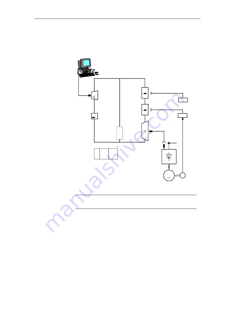
Closed-loop thyristor current control
System- and communication configuring D7-SYS - SIMADYN D
5-3
Edition 06.2002
5.1.1 Hardware configuration
The ITDC converter gating is inserted on a PM5 or PM6 processor and
screwed into place. The modules have a local expansion bus (LE bus) via
which signals and data are transferred.
~3AC
X01
PM5 / 6
9pin
X5
serial
interface
(service)
SITOR
inter-
face
X7
X6
X5
Ext.Vsyn.
diagnostics sig.
2 analog o/p's
4 dig. outputs
4 dig. inputs
1 incremental
encoder
ITDC
SC12
(20pin)
l = 2m
SU11
SC12
SU11
2 AO
4 DO
4 DI
1 INC
20pin
50pin
20pin
SITOR set
or
interface : SE20.2
LE
bus
10pin
SC57
COM1/2
O p e ra to r c o n tro l d e v ic e
l = 5m
M
T
SC31.2
SC17.2
or
l = 2m
PM 1.
ITxx
2.
ITxx
LE-I1
LE-I3
Interrupt
:
+ ITxx
+ ITDC
ITDC
ITxx
Fig. 5-1
Hardware configuration
NOTE
2 ITDC modules cannot be used on a processor module. However,
combinations with other expansion modules is permitted (e.g. IT41)
The interface: SE20.2 implements the mechanical conversion and the
electrical isolation of the standard SITOR interface from the ITDC to a
6QG5x SITOR cabinet or another drive converter.
SITOR sets 6QG2x and 6QG3x differ in the way that the
current actual value is sensed, the conditioning of the zero crossover
signals and the phase-to-phase voltages.
If a 6QG2x or 6QG3x SITOR set is used with an optional field device
module (excitation option), then the FB FCS is required.
The gating unit has been released for operation with 50 Hz and 60 Hz
line supplies (e.g. for PM5); however, it also has automatic frequency
adaptation in the range from 10 to 530 Hz.


