Closed-loop thyristor current control
System- and communication configuring D7-SYS - SIMADYN D
5-25
Edition 06.2002
5.2.3.1 Fault evaluation and protection
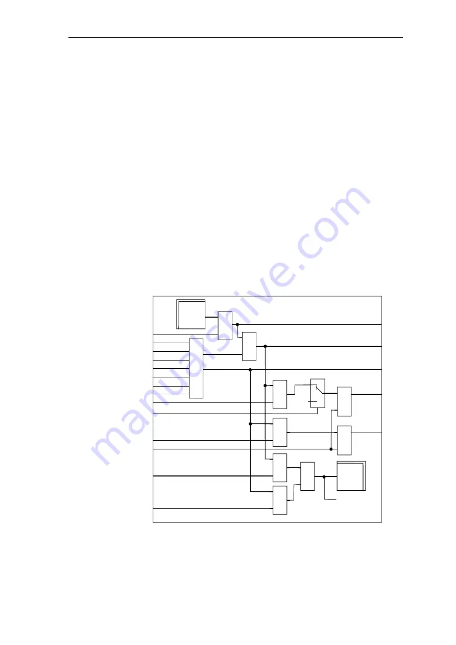
All of the faults are concentrated in the switch-over logic stage where
they can be evaluated.
The faults of the FBs (PA6, EMF, SOL, CAV, PC6, FCS) and two user-
specific, external faults (SOL.IF1 \ IF2) and faults from the ITDC
hardware are combined to two alarm words YW1 and YW2.
Using the masks HM1, HM2, the bits of alarm words YW1 and YW2 are
switched-through into the words for faults YF1 and YF2.
Each bit initiates the “Shift to inverter operation” SOL.OPS=1 and results
in the closed-loop current control being switched-out.
The faults should be acknowledged after the cause has been removed
(QUI=1).
Using the selection masks SOL.HP1, .HP2,
the user decides whether the pulses should be immediately inhibited
SOL.OPL=1.
If this function is enabled, under certain circumstances it can result in
“Inverter commutation faults”!
&
≥1
≥1
&
&
&
&
≥1
0
1
pulse
inhibit
S
R
HMH
//
//
QSC
QSA
QSP
IF1
IF2
QSM
QSS
//
//
//
//
//
YW2
//
YW1
YHW
YW2
//
//
//
//
//
067E
//
//
//
HM1
MNE
HM2
QUI
HP1
HP2
YF1
YF2
HW
fault
ITDC
S
R
ITDC
//
//
inhibit
//
//
= Word size
(YW1)
sol2.dsf
Pulse inhibit
Fault words
//
Fig. 5-12
Function chart SOL - fault evaluation
Function


