Closed-loop thyristor current control
5-10
System- and communication configuring D7-SYS - SIMADYN D
Edition 06.2002
After the line supply is switched-in, it is checked, PA6.NEP. If an attempt
is made to enable the closed-loop thyristor current control (SOL.ION=1)
before this check has been completed, the bits in the fault ID are set at
output PA6.QSF. The closed-loop thyristor current control does not go
into operation. The firing angle controller and therefore the pulses remain
inhibited until a stable line supply is recognized.
Fault signals inhibit closed-loop thyristor current control operation if the
line supply analysis was unsuccessful (refer to Fig. 5-4).
The closed-loop thyristor current control always requires a clockwise
rotating field!
If there is a counter-clockwise rotating field, a fault signal is output and
the closed-loop thyristor current control cannot be switched-in.
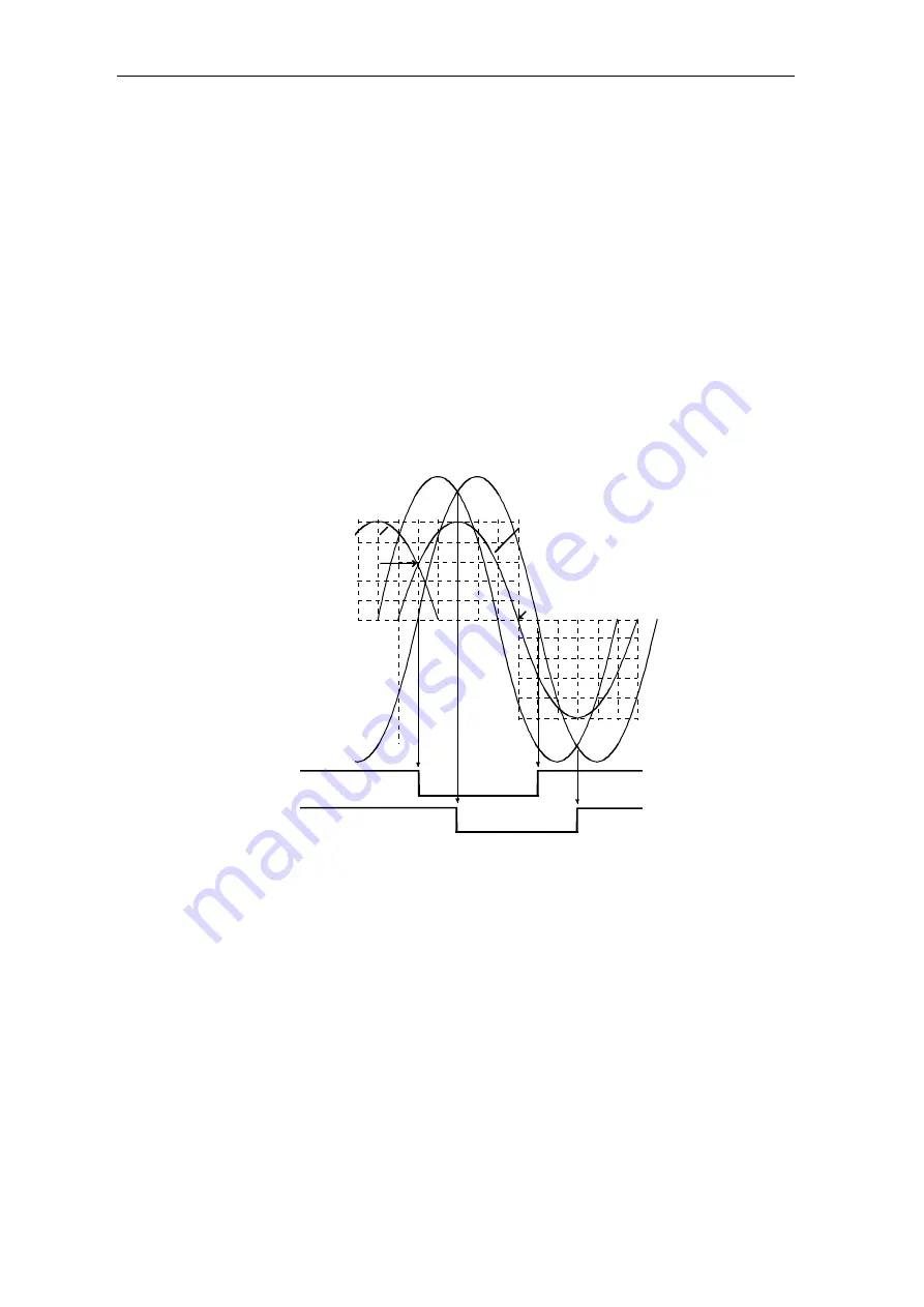
The clockwise rotating field is determined from the phase shift of the zero
crossovers from L1-L2 (V
L12
)
and L1-L3 (V
L13
)
from the Sitor set.
0°
Phase voltage L1
360°
AFI
0
180°
α
=150°el
V
L1-L3
V
L1-L2
L1-L2
L1-L3
L3
0
0
0
α
=0°el
Fig. 5-7
Zero crossovers of the clockwise rotating field
When determining the phase position between the filtered synchronizing
voltage and the zero crossovers of V
L12
and V
L13
, the actual offset angle
is obtained and is output at PA6.YDA in degrees.
XDA
PA
L
V
SYN
V
YDA
PA
.
6
13
.
6
≠
−
=
When making the check, several line supply periods are evaluated.
Output PA6.YDA is a monitoring connection for the commissioning
phase.
Comment
Rotating field
detection


