background image

Communications configuring 


3-284 

System- and communication configuring D7-SYS - SIMADYN D 


Edition 12.2003 


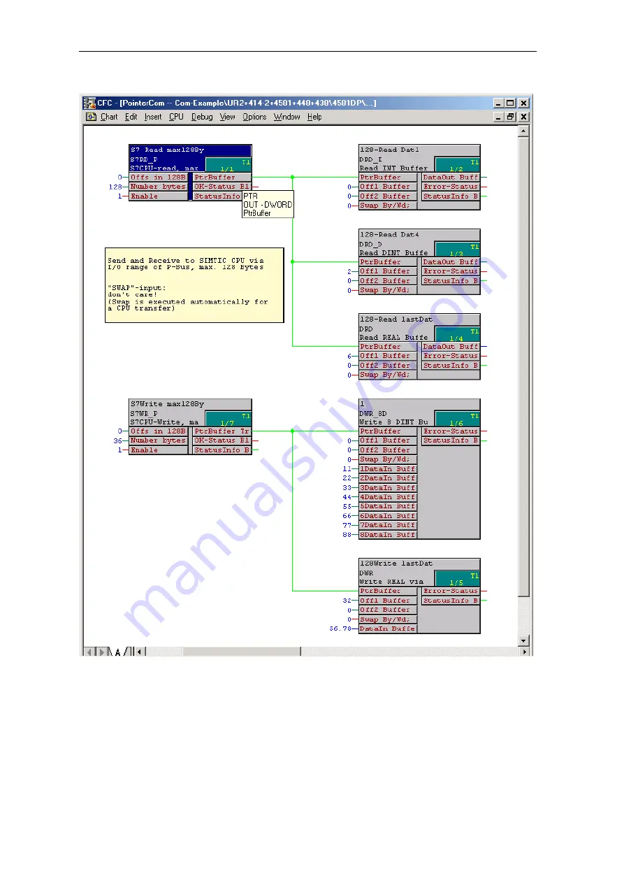
Fig. 3-111  CFC screenshot: Data transfer SIMATIC-CPU 

 FM 458-1 DP via P bus I/O area 


Summary of Contents for D7-SYS

Page 1: ... few steps to the first project Systemsoftware Communications configuring Changeover from STRUC V4 x to D7 SYS Closed loop thristor current control Index System and communication configuring D7 SYS Manual SIMADYN D Edition 12 2003 ...

Page 2: ...cations described in the catalog or the technical description and only in connection with devices or components from other manufacturers which have been approved or recommended by Siemens SIMATIC and SIMADYN D are registered trademarks of Siemens AG Third parties using for their own purposes any other names in this document which refer to trademarks might infringe upon the rights of the trademark ...

Page 3: ...different editions of the individual chapters The following overview tells you when a chapter was revised the last time Chapter Edition Foreword Edition 12 2003 1 In just a few steps to the first project Edition 12 2001 2 Systemsoftware Edition 03 2001 3 Communications configuring Edition 12 2003 4 Changeover from STRUC V4 x to D7 SYS Edition 03 2001 5 Closed loop thyristor current control Edition...

Page 4: ...ease contact your local Siemens office You can also call the Hotline Tel 49 9131 98 5000 Fax 49 9131 98 1603 e mail adsupport siemens com Appropriate training courses are available in order to make it easier to get to know the SIMADYN D automation system Please contact the central Training Center in D Erlangen I S IS INA TC Tel 49 9131 7 27689 27972 Fax 49 9131 7 28172 Internet www siemens de sibr...

Page 5: ...ve changed over STRUC V4 x with the introduction of SIMATIC D7 SYS STEP 7 option packages for D7 SYS Basis software This section explains the essential use and the functions of the STEP 7 automation software For first users it provides an overview on configuring programming and commissioning a station When working with the basis software you can access the online help which provides you with suppo...

Page 6: ...rica Nuremberg Technical Support Local time Mon Fri 7 00 to 17 00 Tel 49 0 180 5050 222 Fax 49 0 9131 98 1603 49 0 911 895 7001 or 49 0 180 5050 223 E Mail tdc support siemens com GMT 1 00 Europe Africa Nuremberg Authorization Local time Mon Fri 7 00 to 17 00 Tel 49 0 911 895 7200 Fax 49 0 911 895 7201 E Mail authorization nbgm siemens de GMT 1 00 America Johnson City Technical Support and Authori...

Page 7: ...Foreword vi System and communication configuring D7 SYS SIMADYN D Edition 12 2003 ...

Page 8: ...g the connection online 1 13 1 6 2 Generating a connection online 1 13 1 6 3 Changing the parameterization online 1 13 1 6 4 Inserting a block online 1 13 1 6 5 Deleting blocks online 1 13 1 7 Results 1 14 1 8 Archiving the project 1 14 2 Systemsoftware 2 1 2 1 Configuring 2 2 2 1 1 General description 2 2 2 1 1 1 Configuring tools 2 2 2 1 1 2 Configuring steps 2 3 2 1 1 3 Terminology and librarie...

Page 9: ...ing its own basic clock cycle to an interrupt task of a master CPU 2 28 2 1 8 4 Synchronizing its own interrupt tasks to interrupt tasks of a master CPU 2 28 2 1 8 5 Synchronizing several SIMATIC TDC SIMADYN D stations 2 28 2 1 8 6 Response when the synchronization fails 2 28 2 1 8 7 Configuring the CPU basic clock cycle synchronization 2 28 2 1 8 8 Configuring the interrupt task synchronization 2...

Page 10: ...edging 3 28 3 3 5 Restart frequency 3 29 3 3 6 Configuring 3 30 3 4 Industrial Ethernet coupling SINEC H1 3 31 3 4 1 Hardware and central coupling block 3 32 3 4 1 1 Hardware 3 32 3 4 1 2 Central coupling block CSH11 3 34 3 4 2 Communications via SINEC H1 layer 2 3 34 3 4 3 Communications via SINEC H1 layer 4 3 36 3 4 4 Communications via SINEC H1 layer 7 STF 3 38 3 4 4 1 Address connections 3 38 ...

Page 11: ...4 3 6 1 3 Communications via PROFIBUS FDL 3 85 3 6 2 Data quantities sampling times 3 87 3 7 PROFIBUS FMS coupling SINEC L2 FMS 3 88 3 7 1 Hardware and central coupling block 3 90 3 7 1 1 Hardware for the PROFIBUS FMS coupling 3 90 3 7 1 2 Central coupling block CSL2F for PROFIBUS FMS coupling 3 90 3 7 2 Communications via PROFIBUS FMS 3 91 3 7 3 SIMADYN D communications utility 3 94 3 7 3 1 Proce...

Page 12: ...Mode of operation 3 143 3 13 6 USS master on the T400 technology module 3 144 3 13 6 1 Basis network for the T400 technology module 3 144 3 13 6 2 Initialization 3 145 3 13 6 3 Broadcast 3 145 3 13 7 Literature 3 145 3 14 USS slave coupling 3 146 3 14 1 Basis network for the T400 technology module 3 146 3 14 2 Initialization 3 146 3 14 3 Exchanging process data 3 147 3 14 3 1 Transmitting 3 147 3 ...

Page 13: ...nserting tabular values in the data block 3 188 3 18 3 3 1 Manually entering tabular values 3 188 3 18 3 3 2 Importing tabular values 3 192 3 18 3 3 3 Subsequently downloading tabular values into a DB 3 202 3 18 3 4 Structure of the data telegram for TCP IP or DUST1 connection 3 204 3 18 4 Automatic mode Memory card 3 205 3 18 4 1 Generating a table file in the csv format 3 205 3 18 4 2 Working wi...

Page 14: ... 21 3 7 Output format of the message evaluation block MSPRI 3 251 3 22 Communications utility parameter processing 3 254 3 22 1 Master configuring 3 254 3 22 1 1 Description of scope 3 254 3 22 1 2 Supported couplings 3 255 3 22 1 3 Telegram structure 3 255 3 22 1 4 Mode of operation of the PKW blocks 3 255 3 22 1 5 Configuring example 3 257 3 22 1 6 Task response IDs 3 260 3 22 1 7 Task response ...

Page 15: ...th SIMATIC Operator Panels 3 292 3 27 1 Configuring example 3 292 3 27 2 Configuring SIMADYN D 3 293 3 27 2 1 Selecting the components in HWConfig 3 293 3 27 2 2 Configuring with CFC 3 294 3 27 2 2 1 Initializing the OP7 3 295 3 27 2 2 2 Reading function block connections I O 3 295 3 27 2 2 3 Writing function block connections 3 296 3 27 2 2 4 Configuring events 3 297 3 27 2 2 5 Configuring alarm ...

Page 16: ... Input output blocks 4 8 4 1 6 Communication blocks 4 9 4 1 7 Conversion blocks 4 13 4 1 8 Diagnostic blocks 4 14 4 1 9 SIMOVERT D block 4 14 4 1 10 COROS blocks 4 15 4 2 Adapting specific connection attributes 4 16 4 2 1 Display utility 4 16 4 2 2 Equipment response utility 4 17 4 2 3 Changing the data types for function blocks 4 17 4 3 Hardware differences 4 18 4 4 Communications 4 20 4 5 Config...

Page 17: ...5 51 5 3 2 Entering the characteristic system quantities 5 52 5 3 3 Current sensing calibration 5 55 5 3 4 Voltage sensing calibration 5 56 5 3 5 Determining the offset angle 5 56 5 3 6 Determining the armature time constant TA 5 57 5 3 7 Optimizing the current controller 5 59 5 3 8 Field supply 5 61 5 4 Special features issues 5 63 5 4 1 Operation from 60 Hz line supplies 5 63 5 4 2 Operation wit...

Page 18: ...g the connection online 1 13 1 6 2 Generating a connection online 1 13 1 6 3 Changing the parameterization online 1 13 1 6 4 Inserting a block online 1 13 1 6 5 Deleting blocks online 1 13 1 7 Results 1 14 1 8 Archiving the project 1 14 2 Systemsoftware 2 1 2 1 Configuring 2 2 2 1 1 General description 2 2 2 1 1 1 Configuring tools 2 2 2 1 1 2 Configuring steps 2 3 2 1 1 3 Terminology and librarie...

Page 19: ...ing its own basic clock cycle to an interrupt task of a master CPU 2 28 2 1 8 4 Synchronizing its own interrupt tasks to interrupt tasks of a master CPU 2 28 2 1 8 5 Synchronizing several SIMATIC TDC SIMADYN D stations 2 28 2 1 8 6 Response when the synchronization fails 2 28 2 1 8 7 Configuring the CPU basic clock cycle synchronization 2 28 2 1 8 8 Configuring the interrupt task synchronization 2...

Page 20: ...edging 3 28 3 3 5 Restart frequency 3 29 3 3 6 Configuring 3 30 3 4 Industrial Ethernet coupling SINEC H1 3 31 3 4 1 Hardware and central coupling block 3 32 3 4 1 1 Hardware 3 32 3 4 1 2 Central coupling block CSH11 3 34 3 4 2 Communications via SINEC H1 layer 2 3 34 3 4 3 Communications via SINEC H1 layer 4 3 36 3 4 4 Communications via SINEC H1 layer 7 STF 3 38 3 4 4 1 Address connections 3 38 ...

Page 21: ...4 3 6 1 3 Communications via PROFIBUS FDL 3 85 3 6 2 Data quantities sampling times 3 87 3 7 PROFIBUS FMS coupling SINEC L2 FMS 3 88 3 7 1 Hardware and central coupling block 3 90 3 7 1 1 Hardware for the PROFIBUS FMS coupling 3 90 3 7 1 2 Central coupling block CSL2F for PROFIBUS FMS coupling 3 90 3 7 2 Communications via PROFIBUS FMS 3 91 3 7 3 SIMADYN D communications utility 3 94 3 7 3 1 Proce...

Page 22: ...Mode of operation 3 143 3 13 6 USS master on the T400 technology module 3 144 3 13 6 1 Basis network for the T400 technology module 3 144 3 13 6 2 Initialization 3 145 3 13 6 3 Broadcast 3 145 3 13 7 Literature 3 145 3 14 USS slave coupling 3 146 3 14 1 Basis network for the T400 technology module 3 146 3 14 2 Initialization 3 146 3 14 3 Exchanging process data 3 147 3 14 3 1 Transmitting 3 147 3 ...

Page 23: ...nserting tabular values in the data block 3 188 3 18 3 3 1 Manually entering tabular values 3 188 3 18 3 3 2 Importing tabular values 3 192 3 18 3 3 3 Subsequently downloading tabular values into a DB 3 202 3 18 3 4 Structure of the data telegram for TCP IP or DUST1 connection 3 204 3 18 4 Automatic mode Memory card 3 205 3 18 4 1 Generating a table file in the csv format 3 205 3 18 4 2 Working wi...

Page 24: ... 21 3 7 Output format of the message evaluation block MSPRI 3 251 3 22 Communications utility parameter processing 3 254 3 22 1 Master configuring 3 254 3 22 1 1 Description of scope 3 254 3 22 1 2 Supported couplings 3 255 3 22 1 3 Telegram structure 3 255 3 22 1 4 Mode of operation of the PKW blocks 3 255 3 22 1 5 Configuring example 3 257 3 22 1 6 Task response IDs 3 260 3 22 1 7 Task response ...

Page 25: ...th SIMATIC Operator Panels 3 292 3 27 1 Configuring example 3 292 3 27 2 Configuring SIMADYN D 3 293 3 27 2 1 Selecting the components in HWConfig 3 293 3 27 2 2 Configuring with CFC 3 294 3 27 2 2 1 Initializing the OP7 3 295 3 27 2 2 2 Reading function block connections I O 3 295 3 27 2 2 3 Writing function block connections 3 296 3 27 2 2 4 Configuring events 3 297 3 27 2 2 5 Configuring alarm ...

Page 26: ... Input output blocks 4 8 4 1 6 Communication blocks 4 9 4 1 7 Conversion blocks 4 13 4 1 8 Diagnostic blocks 4 14 4 1 9 SIMOVERT D block 4 14 4 1 10 COROS blocks 4 15 4 2 Adapting specific connection attributes 4 16 4 2 1 Display utility 4 16 4 2 2 Equipment response utility 4 17 4 2 3 Changing the data types for function blocks 4 17 4 3 Hardware differences 4 18 4 4 Communications 4 20 4 5 Config...

Page 27: ...5 51 5 3 2 Entering the characteristic system quantities 5 52 5 3 3 Current sensing calibration 5 55 5 3 4 Voltage sensing calibration 5 56 5 3 5 Determining the offset angle 5 56 5 3 6 Determining the armature time constant TA 5 57 5 3 7 Optimizing the current controller 5 59 5 3 8 Field supply 5 61 5 4 Special features issues 5 63 5 4 1 Operation from 60 Hz line supplies 5 63 5 4 2 Operation wit...

Page 28: ...teps to the first project 1 1 Prerequisites 1 2 1 2 Creating a new project 1 5 1 3 Defining the hardware 1 5 1 4 Generating a CFC chart 1 6 1 5 Testing compiling and downloading the project 1 10 1 6 Testing the user project 1 12 1 7 Results 1 14 1 8 Archiving the project 1 14 Section overview ...

Page 29: ...ructions are provided in the particular readme files Please observe the interdependencies between versions When installing STEP7 you will be prompted for the online interface however for SIMADYN D nothing has to be selected and installed Close window and exit the following window with OK You will require the following hardware components for the My First Project project example Components Function...

Page 30: ...especially fast as it is directly screwed to the CPU module and the backplane bus is not used 6DD1606 3AC0 Interface cable SC 54 Length 2 m connects the inputs outputs of the IT41 module with up to 5 SBxx or SU12 interface modules 6DD1684 0FE0 Interface module SB10 2 x 8 screw terminals LED displays allows you to test the user program during commissioning and in operation as the statuses of the di...

Page 31: ...ine and change it on the SIMADYN D modules 5 Archive the project You can subsequently apply this procedure for you own applications The task comprises two sections 1 A sawtooth generator with a fixed frequency outputs its value via a D A converter 2 Running Lights with 8 channels To start off with define the individual functions for the appropriate sub tasks and define the necessary hardware 1 Saw...

Page 32: ...d up 5 Open it if required the hardware catalog with View Catalog The hardware catalog with all of the available family of modules is opened 6 Select the SR6 from the SIMADYN D family of modules and Catalog Subracks and drag it to the upper window The subrack is displayed with six slots 7 Locate them one after the other CPU Modules PM5 at slot 1 Expansion Modules IT41 at slot 2 Slot covers SR81 at...

Page 33: ...FC The CFC 1 and CFC 2 charts are displayed as new objects at the righthand side of the project window 16 Select chart CFC2 in the project window and open the properties dialog box with Edit Object properties Enter the sawtooth generator name Click on OK You obtain the properties dialog box of the CNC chart The Properties dialog box is closed 17 Repeat step 16 with the CFC2 chart and re name it Ru...

Page 34: ...log box to interconnect the object with Insert Connect to operand Then mark the selection window Select the first entry and click on OK The block inputs are parameterized The hardware address of the first analog output channel is assigned 25 In the sawtooth block click on output Y and after this on input X in the analog output block The sawtooth generator is connected to the analog output All chan...

Page 35: ...In just a few steps to the first project 1 8 System and communication configuring D7 SYS SIMADYN D Edition 12 2001 Fig 1 2 Sawtooth generator chart ...

Page 36: ...In just a few steps to the first project System and communication configuring D7 SYS SIMADYN D 1 9 Edition 12 2001 Fig 1 3 Running lights chart ...

Page 37: ...ges using Details The result is displayed in a dialog window You have created your first user project 1 5 2 Downloading the user project into the SIMADYN D CPU module SIMADYN D allows you to download online or offline Maybe you do not have a connection from your PC PG to the SIMADYN D station which is why you can use the possibility of downloading into a memory module Step Procedure Result 28 Sele...

Page 38: ... Acknowledge with yes and then close the dialog window Select the interface used and acknowledge with OK You obtain a dialog window in which you can decide by entering either Yes or No whether you wish to immediately go online The Set PG interface dialog window is displayed where you can select the access route DUST1 COM1 or DUST1 COM2 32 Select the Target system Download You obtain the dialog win...

Page 39: ...layed If they match the result is The configuring and the CPU program match You have checked that the PG PC and the SIMADYN D station can communicate 36 Select the menu command Test Test settings Enter the refresh period for the screen display in tenths of seconds Acknowledge the change with OK In the test mode the values of the I O are updated cyclically on the screen with the selected refresh pe...

Page 40: ...O to which this connection should be made The connecting line between the selected I O is generated and the actual parameter value which is presently being transferred is displayed at the output 1 6 3 Changing the parameterization online Select the block input whose parameter value is to be changed by double clicking The dialog box Properties I O is displayed in which you can change the value You ...

Page 41: ...ion The following table shows the assignment of the pins at output connector X6 of expansion module IT41 The output voltage range extends from 10 V to 10 V Pin Function Output 15 Analog output 1 Sawtooth 48 Ground Table 1 1 Excerpt from the pin assignment of IT41 connector X6 You can observe the running light function at the LED display of interface module SB10 1 8 Archiving the project Step Proce...

Page 42: ...System and communication configuring D7 SYS SIMADYN D 2 1 Edition 03 2001 2 Systemsoftware 2 1 Configuring 2 2 2 2 Function description and user instructions 2 41 2 3 System chart SIMD 2 45 Overview ...

Page 43: ...ser Manual This Manual is sub divided into the following Chapters General description Configuring the hardware Creating CFC charts Operating statuses of a CPU module Configuring example for a CPU module Using signal transfer mechanisms Significance and uses of the process image Significance and uses of the CPU synchronization Significance of processor utilization To implement most of the applicati...

Page 44: ...and special characters A Z Second character Alphanumeric characters and special characters A Z 0 9 _ or if the first character is Additional characters Alphanumeric characters and special characters A Z 0 9 _ Table 2 1 Nomenclature when assigning names to modules Chart and function block names when both names are connected the total number of characters may not exceed 24 Name Max length Permitted ...

Page 45: ...to configure the hardware of SIMATIC TDC SIMADYN D stations A SIMATIC TDC SIMADYN D station consists of a rack with up to 20 8 CPUs and other hardware modules When required several stations can be coupled with one another The modules to be configured can be selected from the modules in the HWConfig hardware catalog Racks CPUs I O modules coupling modules etc can be selected HWConfig defines the sy...

Page 46: ...ual modules which can be selected Using HWConfig a module is configured possibly with a sub module for every subrack slot This provides a precise image of the rack as it is in reality while the hardware is being configured When selected each module is given a name recommended which can be changed in accordance with the syntax for names Slot covers must be provided for those slots which remain empt...

Page 47: ...Serial couplings Dxy__C xy xy slot number Other modules Dxy xy xy slot number Table 2 4 Designation schematic for the hardware configuration in HWConfig The slot number of a module specifies the number of the slot in the subrack where the actual module is configured For a SR24 with 24 slots these are slots 1 to 24 All sub modules of a module are consecutively numbered starting from 1 The sub modul...

Page 48: ...ated to block diagrams A CFC comprises of several CFC charts each with 6 sheets Each sheet can have a different number of various function blocks The actual number is only limited by the graphic layout In the overview of the CFC editor all 6 sheets of a chart are displayed and in the sheet view an individual sheet can be displayed in detail The function blocks which can be called up in the CFC edi...

Page 49: ...nction block defined under function block insert can be changed within a task The selected function block can be searched for cut out in the execution sequence and inserted in another position I O The following I O data can be entered here for all parameters value and comment for input and output parameters visibility in the CFC chart for parameters which are not interconnected set or inhibit para...

Page 50: ...ntrolled when they are called up or in the execution sequence of the CFC editor they are entered in the required sequence under one of the 8 possible process interrupts Thus individual function blocks or a run time group can be executed initiated by a specific process interrupt NOTE Contrary to cyclic tasks interrupt tasks are not started in equidistant time intervals but when a process interrupt ...

Page 51: ...CFC charts e g e g Fig 2 1 Function block processing by the operating system The actual open loop and closed loop control task can be implemented using SIMATIC TDC SIMADYN D almost the same as in a block diagram by interconnecting and parameterizing the function blocks A function block type can be used as often as required The function blocks are parameterized and interconnected at the block input...

Page 52: ...nd outputs are pre assigned but these can be changed The outputs can be connected to other inputs or assigned an initialization value which is different than the pre assigned value This value is available at this output if the function block is executed for the first time in the INIT operating status This is practical if the output of a flipflop block is to be pre assigned The margins at the left ...

Page 53: ...function blocks or via any links using the process data utility a symbolic hardware address A hardware address is in this case a symbolic designation of one or several associated terminals of a module For example binary inputs of a binary input module The symbolic hardware address is defined in the HWConfig program section a name reference i e the name of a message system All types of interconnect...

Page 54: ...r number 0000 to 9999 Additional information on parameters and technology connectors refer to Manual SIMADYN D Control System Communications Configuring D7 SYS Section Parameterizing SIMADYN D 2 1 3 3 The third step Compiling and loading the user program into the CPU After all of the required hardware modules have been configured with HWConfig and the required function blocks on the individual cha...

Page 55: ...al system error processing aborted 7 segment display Dark 0 PN number 1 8 and C E b A d flashing when downloading 0 the cause flashes H the cause flashes Red LED on T400 Dark Off Flashes at a low frequency Flashes at a medium frequency Flashes at a high frequency Lit bright Available diagnostic interfaces None All of those configured one must be at the first CS7 SS and local interface Local interf...

Page 56: ...erface local or configured In this status all configured service interfaces and the local service interface are still available i e diagnostics and downloading are still possible via all of the service interfaces this is necessary if several PCs are connected at the rack 2 1 5 Configuring example of a CPU module The procedure when generating a new project with the HWConfig and CFC configuring tool...

Page 57: ...drop or clicking twice with the mouse The hardware can be parameterized differently than that pre assigned by double clicking on the CPU or on the memory module in the subrack Before HWConfig is terminated the entered hardware configuration is checked via the menu bar Station Check consistency HWConfig can then be closed via Station Save and Station Terminate Now select the Charts directory locate...

Page 58: ... 2 1 6 1 Data consistency For interconnections between different cyclic tasks SIMATIC TDC SIMADYN D ensures the consistency of all data which is transferred This means that all data transferred from a task come from the same computation cycle of this task All values calculated during a sampling cycle are exported at the end of the task When starting a task the required values are imported whereby ...

Page 59: ...ing to the signal flow i e that block whose outputs are used as inputs for the following block is first computed etc 2 1 6 3 Data transfer between various CPU tasks Data transfer between various tasks of a CPU is realized via a buffer system so that the data consistency can be guaranteed refer to the Chapter Data consistency However for data transfer from a faster to a slower task it should be obs...

Page 60: ...ithin the same SIMADYN D station menu item Insert connection to the operand in the CFC editor The following data are required to configure a signal the signal name type bus assignment The dollar signal type defines whether data transfer is to be consistent standard or inconsistent fast signal For a fast signal the user destination can always access a current value The deadtime generated during sig...

Page 61: ...al is generated or used in an interrupt task This is the because an interrupt event can occur at any instant in time and therefore the consistency mechanisms must be bypassed in order to prevent data loss In this case a conflict could occur between the demand for data consistency and low deadtimes A decision must now be made depending on the particular application NOTE It should always be checked ...

Page 62: ...he task processing Buffer changeover for the tasks to be started T1 and if required an additional task Tn System mode of the blocks in T1 corresponding to the module sequence refer to the Chapter Significance and uses of the process image System mode of blocks in Tn corresponding to the block sequence refer to the Chapter Significance and uses of the process image Importing signal interconnections...

Page 63: ...n additional differentiation is made between standard and fast signals For interconnections between tasks of a CPU the alternating buffer system on the processor is used The maximum number of interconnections is limited by the main memory expansion stage Connections between several CPUs of a station are handled via the communication buffer modules The number of possible interconnections is depende...

Page 64: ...m mode of the function blocks when a task is started to be processed The task administrator refer to the Chapter Mode of operation of the task administrator of the operating system is started with the basic CPU clock cycle T0 This decides which tasks are to be started T1 and a maximum of additional Tn with Tn ε T2 T5 Within the task processing the following components are to be executed Buffer cha...

Page 65: ...ed within the process image so that the results can be subsequently consistently used in the standard mode System mode Standard mode 10 30 Tx Ix Processing by the operating system Function block Explanation of symbols Process image Remaining cycle 10 20 30 35 40 Fig 2 6 Sequence of the function block computation in the system and standard modes The system mode starts immediately after the initiati...

Page 66: ...outputs Value s in the buffer memory Value s from the buffer memory Sampling time TA n Sampling time TA n 1 System mode Normal mode Fig 2 7 Sequence of the system mode for input blocks For output blocks which have a system component and whose system component is activated in the standard mode of the previous cycle the signals to be output are calculated corresponding to the block function and the ...

Page 67: ...e read in immediately before being computed and for output blocks immediately after their computation 2 1 7 3 Process image for interrupt tasks An interrupt task has essentially the same behavior as a cyclic task An interrupt task can interrupt a cyclic task running in the standard mode However it cannot be interrupted by cyclic tasks Thus e g for longer computation times of an interrupt task the ...

Page 68: ...t tasks of a master CPU Synchronizing several stations Response when synchronization fails Configuring the CPU basic clock cycle synchronization Configuring the interrupt task synchronization 2 1 8 1 Time synchronization The real time clocks of all CPUs in a SIMATIC TDC SIMADYN D station are synchronized to the clock of CPU inserted at slot 1 This prevents the various CPU clocks from drifting apar...

Page 69: ...hronize the basic sampling time over several stations In this case the bus systems of the two stations are connected via coupling modules Further information on synchronization please refer to the System and communication configuring D7 SYS Manual 2 1 8 6 Response when the synchronization fails The basic clock cycle is monitored on the synchronized receiver CPUs using a hardware timer If the trans...

Page 70: ...the basic clock cycle The appropriate bus must be set for this purpose No is pre assigned default If the basic clock cycle is to be synchronized to another source HWConfig requires the following settings Activate the Synchronizing button with a mouse click Select the required source from a list e g L or C bus basic clock cycle L or C bus interrupt SIMADYN D bus interrupt SIMATIC TDC Enter an equiv...

Page 71: ...hronization is disabled as default i e no process interrupts are defined and a bus interrupt is not transmitted The mouse is used to select one of the 8 possible interrupt tasks I1 I8 Select the required source of the defined process interrupt from a list e g C bus interrupt or CPU counter C1 or C2 Enter an equivalent sampling time from 0 1 to 16 ms In the lower window section select whether the s...

Page 72: ... line CPU 3 retrieves its basic clock cycle from the L bus interrupt line and switches the interrupt received via the binary input configuration with function block PAI to the C bus interrupt line 2 1 9 Significance of the processor utilization 2 1 9 1 Determining the approximate processor utilization When compiling the CFC determines a value for the CPU computation time utilization A list is acce...

Page 73: ...ed Further the PSL block has 5 inputs T1 5 which for each task can be used to simulate an additional load in milliseconds ms It is then possible to read how such a load effects the utilization of the individual tasks at the outputs The utilization is determined by measuring the task run times and then dividing this by the actual sampling time Higher priority tasks occur within the run time of a ta...

Page 74: ... CPU if this is the highest priority error status of the CPU at this time In addition to the configurable interrupt tasks the cyclic tasks are interrupted especially by communication interrupts These interrupts ensure that for example the data to be transmitted and received via the serial interfaces is processed before new data is received Transmit and receive interrupts such as these can occur in...

Page 75: ...ective way to achieve the desired result 2 1 10 Technical data of the operating system 2 1 10 1Features The most important properties and technical data of the operating system are specified in the following A maximum of 8 SIMADYN D or 20 SIMATIC TDC CPU modules can be inserted in a subrack A CPU module requires 1 slot Slots which are not occupied by CPU modules can have peripheral modules The max...

Page 76: ...t 8 MHz The minimum time is shown in the following table which is required to process each cycle of a task refer above for the basis for the calculations Time to start 40 µs Time to end 40 µs Additional component for a local buffer system 20 µs C bus buffer system 20 µs L bus buffer system 20 µs Table 2 12 Computation times of the operating system The code and data of the operating system are copi...

Page 77: ...e operating system is capable of multi processing and multi tasking The basic operating system functions are embedded in the overall system whereby these represent the most important interfaces to the environment Operating system functions Initiated by Initialization RESET Cyclic processing Sampling time timer Interrupt controlled processing Process interrupts Process image Exception handling and ...

Page 78: ...g sampling time The task administrator is started with the clock cycle of the basic sampling time of the sampling time timer This determines the second task task Tn to be started in addition to T1 Tn from T2 T5 If the task to be started has a lower priority than an interrupted task its start is buffered and the interrupted task is continued Otherwise the determined task is started The status of th...

Page 79: ...ued or terminated The system informs the user about its status especially about the error statuses using the 7 segment display on the CPU module When an error situation occurs detailed information is deposited in the error data fields of the operating system These error data fields permit a precise error analysis to be made This data can be read out and changed using the service utility The signif...

Page 80: ...aults crashes run up problems and faults which are caused in the CPU module itself are identified here All activities of the service utility are controlled via tasks which are received via its data interface corresponding to the parameterization of the service function block I O All devices which can process the task and response language of the utility can be used as handling devices for the serv...

Page 81: ...imum of one task per clock cycle For cyclic tasks for each clock a maximum of one response telegram is received The advantage of this mode of operation is that for cyclic tasks equidistant timed responses are obtained If the reserved computation time is not fully utilized because for example there is no task to be processed then this time is made avasilable to the system For multiple configuring w...

Page 82: ... messages A long message is output in the case of a non maskable interrupt NMI A short message for a power OFF The service communications utility is available even if it has not been configured to troubleshoot fatal system errors It can be accessed via the local diagnostics interface after pressing the acknowledge button Using the service utility the error causes can be output in plain text What i...

Page 83: ...ess as above and Status 0xF000FC14 mdlo 0x04C4F19A BadVAddr bad virtual address fpc_csr 0x00000F04 address which was erroneously accessed mainly for ID TLB and CPU CAUTION The value of a0 a1 and possibly a2 is not valid r00 0 0x00000000 r01 at 0x00000000 r02 v0 0x00000001 r03 v1 0xB8803000 r04 a0 0x80064FC8 r05 a1 0x80064F44 r06 a2 0x0000000A r07 a3 0x00000000 r08 t0 0x80064FC4 r09 t1 0x80065048 r...

Page 84: ...s which cannot be divided by four user access to kernel space unaligned load store to coprozessor 0 2 3 unaligned load store to L C bus address space break 6 7 not in div mul context unknown break value reserved exception task running in endless loop FPUFPU exception status fpu fault at non fpu instruction illegal fpu sub opcode operation on NaNs add sub division of infinities mul of infinity and ...

Page 85: ...processing are saved in the UEB element of the error field SYS_ERR 2 2 2 1 Online test mode In the online test mode for example a battery test a memory module checksum test etc are executed The memory module checksum routine determines the memory module checksum and compares it with the checksum calculated by the programmer and that saved in the memory module If a memory module checksum error is i...

Page 86: ...eld CER Communication error Task administrator error field TER Task management error Hardware failure Monitoring error HER HW error User error field UER User error Evaluate errors DER Display error Display Output 7 segment display DST Display status Output diagnostics LED DST Output status word SIMS status bit SIMD SIMS SIMD Table 2 14 Detailed information on system chart SIMD The operating system...

Page 87: ...vention at connection ACK000 I set from 1 to 0 Priority controlled error fields and therefore their display are acknowledged using this pulse Output of error codes C and E can be suppressed by changing the ACK050 I connection from 0 to 1 The components are evaluated using the function blocks SYF1 and SYF4 The appropriate numbers of the errors fields are documented in the function block description...

Page 88: ...or source is still present Before an error can be removed the error cause must be determined and removed When there are no errors the processor number is displayed on the 7 segment display If a component signals an error then the appropriate error code is output The status display on a T400 is realized via a diagnostics LED The flashing clock cycle is increased if the error is a first error The st...

Page 89: ... in the user program The error outputs of the individual components are combined to form an error status word via the SIMS function block The SIMD Q output connection represents a general error status The error status word at the SIMS QS block connection has the following bit assignment Bit Bit assignment Bit1 Unused Bit2 Unused Bit3 Unused Bit4 Task administrator error Bit5 Unused Bit6 Hardware f...

Page 90: ...o peer coupling 3 149 3 16 SIMATIC P bus coupling 3 151 3 17 SIMOLINK drive coupling 3 160 3 18 Table function 3 177 3 19 Parameter access technique for D7 SYS 3 214 3 20 Communications utility display control 3 229 3 21 Communications utility message system 3 239 3 22 Communications utility parameter processing 3 254 3 23 For change tasks the parameter change rights of the drive converter must be...

Page 91: ...upling defines the hardware e g CS7 SS52 and the data transfer protocol e g PROFIBUS DP for communications The particular application and communication capabilities of the partner define the communications interface and the data coupling 3 1 1 1 Overview of the various data couplings Couplings are configured in the CFC application using the central coupling blocks Used for the communications partn...

Page 92: ... 4 slaves CS14 master for 8 slaves Hardware required Communications module for the slave interface CS22 Communication utility Process data message system trace Central coupling block CS1 CS2 Features Fiber optic cable CS12 Point to point coupling with CS22 slave interface CS13 Coupling with 4slave interfaces CS22 CS14 Coupling with 8 slave interfaces CS22 CS22 Coupling with master interfaces CS12 ...

Page 93: ...d using the NML software Table 3 4 Industrial Ethernet coupling SINEC H1 Used for the communications partner SIMATIC S5 S7 SIMOVERT SIMOREG drive converters ET200 SIMADYN D Certified third party equipment devices Hardware required CS7 communications module with SS52 communications module Communications utility Process data Parameter processing Central coupling block CSPRO Features Standardized mul...

Page 94: ...x 1 5 Mbaud Maximum net data length 232 bytes Table 3 6 PROFIBUS FDL coupling Used for the communications partner SIMADYN D only if PROFIBUS FMS is used as a result of other communication partners SIMATIC S5 S7 Certified third party equipment devices Hardware required Master CS7 communications module with SS5 communications module Communications utility Process data Message system Central coupling...

Page 95: ... Features Low cost point to point connection 2400 4800 9600 or 19200 baud Either a 20 mA or V 24 interface can be used Maximum net data length 248 bytes Table 3 8 DUST 1 coupling Used for the communications partner Printer Hardware required CS7 communications module with SS4 communications module Communications utility Message system Central coupling block CSD02 Features Low cost point to point co...

Page 96: ...tocol e g Allen Bradley Hardware required CS7 communications module with SS4 communications module Communications utility Process data Central coupling block CSD03 Features Point to point connection 3964 R data transfer protocol with without RK512 communications protocol 2400 4800 9600 or 19200 baud Either 20mA or V 24 interface possible Maximum net data length 750 bytes Table 3 10 DUST3 coupling ...

Page 97: ...19 2 38 4 93 75 or 187 5 kbaud For drive converters Maximum net data length is 28 bytes Table 3 11 USS master coupling Used for the communications partner CFC WinCC SIMATIC OPs Hardware required CS7 communications module with SS52 communications module Communications utility Service S7 communications Central coupling block CSMPI Features Multi master bus with a maximum of 126 nodes 187 5 kbaud Sta...

Page 98: ...ion of all of the CPUs used e g in order to compare messages with a time stamp Special function blocks RTC Data trace Trace process quantities TCP TR Network Transparent data transfer beyond the subrack NMC S7 communications Operator handling and visualization of CPU program CFC Communication function block S7OS Table 3 13 Overview of the communication utilities 3 1 3 Communication block I Os 3 1 ...

Page 99: ...n Available when transmitting AR connection Available when receiving US connection Available for function blocks which are processing a send and a receive channel The data entries at the address connection are independent of types AT AR or US The possible data are Channel name Channel name Address stage 1 Channel name Address stage 1 Address stage 2 The channel name addresses a channel at a data i...

Page 100: ...ficance and contents of the address stages are described for the particular coupling 3 1 3 3 Data transfer mode MOD input There are five various data transfer modi for the various communication requirements handshake refresh select multiple image The data transfer mode is specified at the MOD connection of the appropriate transmitter or receiver The Handshake data transfer mode is used if informat...

Page 101: ...precisely one receiver for each transmitter Refresh overwrites when it transfers data The transmitter always deposits the latest data set in the channel without the receiver having acknowledged that it has received the last data set There are two net data buffers for data transfer which are used as alternating buffer system The transmitter flags in which buffer the latest data are located Transmit...

Page 102: ...ter sampling time than the receiver Trans 1 KVL NDP Trans 2 Trans n Receiver KVL channel NDP net data buffer Fig 3 3 Data transfer in the Select mode The Multiple data transfer mode is used if receivers are to always be provided with the latest data and if as many receivers as required are available for each transmitter Multiple overwrites data when transferring data The transmitter always deposit...

Page 103: ... task wish to send their data to the DP slaves in the same DP cycle To do this transmitter and receiver FBs synchronize themselves within a task in order to supply consistent data They form a so called consistency group All receiver FBs associated with such a consistency group fetch their net useful data from a common alternating buffer and all of the transmitter FBs deposit their data in such a b...

Page 104: ... ECL 0 and ECO 0 The firmware is in an error free condition ECL 0 and ECO 0 The firmware has an error condition which can be rectified by the configuring engineer or user The error cause is described in the Chapters associated with the individual couplings ECL 0 and ECO 0 An irreparable firmware error is present 3 1 3 5 Status display output YTS The block outputs an error code or the instantaneous...

Page 105: ...oupling module Data interface Serial connection connector at the front panel Re structuring and packaging of the data is realized by the firmware on the coupling module Fig 3 6 Data transfer between the CPU and coupling module The C and L buses are structured the same have the same mode of operation and the same performance features The coupling module bus connection defines whether data are trans...

Page 106: ...ializing by the central coupling blocks and the coupling module firmware the central coupling block enables the coupling for all transmitters and receivers in the same subrack Data transfer can now start for timing reasons a coupling is always enabled in the RUN condition after several sampling times Monitoring the central coupling blocks provide information at their outputs about the status of th...

Page 107: ...ss data transmit block CTV Examples of the receivers process data receive block CRV As transmitters and receivers don t differentiate between the individual couplings at the block inputs of the transmitter and receiver a coupling type must not be specified CTS input to specify the coupling module address connection AR AT or US to specify channel names and coupling specific addresses Before transmi...

Page 108: ...dized data type SIMADYN D data type Length in bytes Integer 16 Integer 2 Integer 32 Double Integer 4 Unsigned 8 Bool Byte 1 Unsigned 16 Word 2 Unsigned 32 Double Word 4 Floating Point Real SDTIME 4 Octet String 1 Time and Date 6 Table 3 15 Standardized data types NOTE The SIMADYN D connection types e g SDTIME are not used as data types as the coupling partner does not always have to be a SIMADYN D...

Page 109: ...ck size The largest subrack in the SIMADYN D system has 24 slots As a subrack must have at least one CPU theoretically 23 slots remain available address space In practice these limits are seldomly reached For CS modules the L and C bus each have 1 Mbyte address space The individual CS modules always occupy a constant address space on the backplane bus Example CS7 always occupies 64 Kbyte on the L ...

Page 110: ...ceivers go into a wait condition After enabling channels log on register and synchronize just the same as when the system runs up The subrack coupling is an application Here data areas can be reserved which are not used If individual subracks with a CS22 module are shutdown and the number of transmitters or receivers is reduced due to a configuring change the earlier reserved data areas on the CS1...

Page 111: ...he buffer Only the data at the CTS connection has to be changed at all communication function blocks The CPN central blocks cyclically initialize and monitor the coupling Thus at the start of cyclic operation the coupling is not enabled for all senders receivers but only after a delay of several operating cycles The CPN central block monitors the coupling after the coupling has been enabled A CPN ...

Page 112: ...after the coupling has been enabled The communications buffer coupling can only be used by send receive blocks which are configured on the same subrack For the communications buffer coupling only the channel name has to be specified at the AT AR or US connections of the transmit receive blocks Address stages 1 and 2 do not have to be configured Transmitters and receivers with the same channel name...

Page 113: ... several operating cycles After the coupling has been enabled the CEP central block monitors the coupling NOTE Only communication utility process data can be configured For the coupling to EP3 modules only the channel name has to be specified at the AT and AR I O of the transmit receive blocks Address stages 1 and 2 do not have to be configured For channel names the EP3 modules only evaluate the 5...

Page 114: ...he CS12 CS13 or CS14 modules will be designated as the master subrack in the following The subrack in which the CS22 module is inserted will be designated as the slave subrack One central block CS1 or CS2 must be configured on any CPU in each subrack for coupling initialization and coupling monitoring CS14 CS22 CS22 CS22 Subrack No 1 CS22 16 CS22 CS22 CS22 CS22 8 No 2 No 3 No 4 No 5 No 6 No 7 No 8...

Page 115: ...on configuring D7 SYS SIMADYN D Edition 12 2003 Subrack No 1 No 2 CPU CS12 CPU CS22 Fig 3 11 Point to point coupling with CS12 No 2 Subrack No 1 No 3 No 4 No 5 8 CPU CS13 CS22 CPU CPU CPU CS22 CS22 CS22 CPU Fig 3 12 Configuration for four slaves with CS13 ...

Page 116: ...between the other nodes master and a maximum of seven slaves is not influenced Slave subracks which are powered down can be re configured and powered up again The number of transmitters and receivers can also be changed e g if one transmitter too little was configured As soon as the slave partner which was powered down is powered up again a new connection is established between the new partner whi...

Page 117: ...en manually acknowledging after the connection has been established the E can be acknowledged by depressing the red acknowledge button on the CPU For automatic acknowledgement the following must be configured on all CPUs in the slave subrack which communicate via the subrack coupling Automatic acknowledgement can be implemented in two different ways using this particular configuration 1 All YEV ou...

Page 118: ...hich E is acknowledged Fig 3 13 Automatic acknowledgement of E 3 3 5 Restart frequency An additional important communications feature for external communication interfaces is the restart frequency of transmitters receivers Transmitters receivers always re locate their old channel and re synchronize with them Subracks can be powered up and down again in any sequence The transmitters receivers of th...

Page 119: ...e If the CS1 central block was configured in 100ms the CS2 central blocks can be configured in a sampling time up to 200ms 180ms 150ms 130ms 50ms etc are thus permitted The data interface is located on the dual port RAM of the CS12 CS13 or CS14 module The available data transfer area is 128 kbytes The coupling initialization and monitoring is handled by the CS1 and CS2 central blocks in the RUN st...

Page 120: ...ommunication utilities can communicate via SINEC H1 in this way Layer 7 STF STF SINEC technological functions The data to be transferred are defined as variable object and are processed with STF utilities Read variable Write variable For STF utilities there is always a client and a server The server defines the variable and responds to utility requests the client issues the utility requests SIMADY...

Page 121: ...les Write variable Using this STF utility a client changes the value of a variable at a server The client sends the task Write variable X together with the new values to the server the server acknowledges this Data transport connection The data transport connection is a defined communications path between two bus nodes at OSI layer 4 A data transport connection must be configured using NML It must...

Page 122: ... in the STOP or ADMIN setting Table 3 17 LEDs on the front panel of the CSH11 The ADMIN switch on the CSH11 has three settings RUN All of the data transfer connections have been established and data is being transferred STOP Data transport connections have been established but there is no data transfer The SIMADYN D blocks indicate that data transfer has been temporarily interrupted e g at output ...

Page 123: ...abase incomplete 7 CSH11 in the STOP condition 0 error Any Irreparable error red LED flashes Note the error class and code and contact Siemens AG Table 3 18 Information at the outputs ECL and ECO NOTE If ECO 6 and simultaneously the green LED on the CSH11 is lit the database is consistent then the NML software should be corrected as follows CSH1 SINEC TF00 must be selected under the NML menu item ...

Page 124: ... 1 2 ll 2 Reserved ID when using SINEC H1 layer 2 ll Local Link Service Access Point LLSAP The LLSAP consists of two hexadecimal numbers and must be divisible by four 00 and 08 are not permitted Each LLSAP can be simultaneously used bidirectionally i e transmitting and receiving Either one AT transmit channel and AR connection receive channel can use the same LLSAP or one US connection transmit an...

Page 125: ...e bidirectional NOTE When transferring data it should be observed that the lengths for the transmitters and receivers communicating with one another coincide Otherwise data transfer is transparent i e the CSH11 transfers all data unchecked Word 2 bytes and double word 4 bytes quantities are transferred in the Little Endian format i e the least significant byte at the beginning and then the most si...

Page 126: ...ort connection name Max 12 characters The symbolic name refers to a data transport connection configured with NML The data transport connection name is the only assignment between the SIMADYN D software and the NML software Each data transport connection can be bidirectional i e transmitting and receiving can be simultaneously used Either one AT transmit channel and AR connector receive channel or...

Page 127: ...t adapt appropriately e g for SIMADYN D using the SWB conversion blocks 3 4 4 Communications via SINEC H1 layer 7 STF Communications via SINEC H1 layer 7 is configured at address connections AT and AR NOTE The application associations are configured using the NML configuring tool Further information on the configuring tool NML refer to the User documentation SINEC NML CP141x CP1470 When accessing ...

Page 128: ...of the application association via which the STF utility is handled Application associations are configured with SINEC NML they define the communication paths between the applications The application association name is the only assignment between the SIMADYN D software and the NML software Address stage 2 max 20 characters address stage 2 is the remote variable name for the communications partner...

Page 129: ...e an open structure as far as SINEC H1 is concerned The channel name is specified at connection AR of the receive block A remote client can execute the STF utility Write on this variable The channel name is specified at connection AT of the transmit block A remote client can execute the STF utility Read on this variable The SIMADYN D utility ID at the end of the variable name is P Address examples...

Page 130: ...uring of the virtual connections refer to the Chapter Communications utility process data The SIMADYN D data types are converted into STF data types using the following table SIMADYN D data type STF data type Integer Integer16 Double Integer Integer32 Bool Byte Unsigned8 Word Unsigned16 Double Word Unsigned32 Real SDTIME Floating Point Table 3 19 Converting SIMADYN D data types into STF data types...

Page 131: ...ariable name is M The communications partner must read the object at specific intervals using the STF utility Read If a message was output via a message output block the Read utility will positively respond and return this message otherwise the response is negative Address example The configuring is to be in subrack BGT1 CPU No 3 function block MSI AT MELD the following variable name is obtained M...

Page 132: ...signed8 Unsigned8 Message type description 1 Octet Octet String 2 Message type 1 Octet Only available Prefix Floating Point Floating Point if SNV 1 Suffix Floating Point Floating Point Measured value Floating Point Floating Point Measured value dimension text 8 characters Visible String 32 if STM 0 Visible String 92 if STM 1 Message instant 24 characters Only available if STM 1 Message text 60 cha...

Page 133: ...s buffer module 29 Channel length net data 2048 bytes Number of data transfer connections A maximum of 46 per transmitter and per receiver from SIMADYN D can use layer 4 of the CSH11 46 CP1470 characteristics Fastest layer 4 sampling time up to max 512 bytes If for example 15 transmitters are configured then the transmitters should be configured in a sampling time greater than 15 x 10 ms 150 ms Th...

Page 134: ...ntation SINEC NML CP141x CP1470 When configuring for layer 2 or layer 4 the CSH11_E4_2000 profile should be used If this is not available for the NML version supplied then please contact Siemens AG who will then provide you with it profiles to be imported Mgt Tbez e4_handshake function distribution table to be imported CSH1 SINECTF00 For layer 4 operation data transport data transfer connections m...

Page 135: ...ately Shared input Each slave connected to PROFIBUS DP is assigned just one master the parameterizing master and at first can only communicate with this master Additional masters can read the slave input data using the Shared input SIMADYN D supports this functionality as master and slave SYNC and FREEZE The outputs inputs of several slaves can be read written in synchronism using the SYNC and FRE...

Page 136: ...O A maximum of one transmitter and receiver function block per slave station Maximum of one synchronizing function block SYNPRO can be configured A maximum of one diagnostics function block DIAL2A can be configured The following communication utilities are permitted Process data Parameter processing of variable speed drives Permitted data transfer mode Refresh For receivers optionally also multipl...

Page 137: ...y CFC are valid the module waits for download the existing COM database can also be activated by correcting the baud rate and PROFIBUS address at the central block of the COM configuring 3 5 1 2 Address connections AT AR Special features when making data entries at address connection AT AR when using PROFIBUS DP Input sequence Channelname Adressstage1 Addressstage 2 Channel name max 8 characters A...

Page 138: ...dministration uses the Intel format e g SIMADYN D 2nd character Optional only receiver R The access is realized as second master which reads data R can only be entered for receive channels Shared input If a 2nd character is not specified then the slave can be accessed as parameterizing master AT Setpoint 25 1 the channel with the name setpoint transmits data to a slave with the PROFIBUS address 25...

Page 139: ...smits a FREEZE broadcast telegram to the configured slave group All of the slaves of this group then simultaneously read their inputs and buffer them This input data is then available for the SIMADYN D CPUs after a DP bus circulating time has expired Ensuring data consistency By suitably configuring it should be ensured that during a DP bus circulating time after the FREEZE command has been initia...

Page 140: ...l transmit blocks and the SYNPRO function block must be configured in the same sampling time the SYNPRO function block must be configured before all of the transmit blocks sequence of execution output SOK of function block SYNPRO must be connected with the enable inputs of all transmit blocks belonging to a slave group the bus circulating time must be shorter than the Synccycle minus 1 x sampling ...

Page 141: ...onfigured in the same sampling time high baud rate 1 5 Mbaud For lower baud rates the time conditions can hardly be maintained the bus circulating time may only be a maximum of 50 of the sampling time the bus circulating time must also be so low that one sampling time expires from the start up to the calculation of the function block SYNPRO This cannot be guaranteed but must be checked when the sy...

Page 142: ...ed in the jitter Configure the SYNPRO function block and all associated transmit blocks in T1 T0 basic sampling time The SYNC command is always initiated with the basic clock cycle interrupt It is received with more accuracy timing accuracy as an interrupt initiated in the system mode Configuring version 1 3 is for generally less frequently used applications of FREEZE Generating SYNC and FREEZE or...

Page 143: ...e bus circulating time one sampling time SOK 0 The transmit and receive blocks are enabled in the fourth sampling time after the SYNC command has been initiated SOK 1 3 5 1 5 Diagnostics function block Master or slave specific diagnostic information can be output from PROFIBUS DP using the DIAPRO function block The diagnostic data to be output are selected using input SEL It is output at D01 to D0...

Page 144: ...er list provides an overview of the slaves which were involved with data transfer within a configured time COM PROFIBUS The 8 words are bit coded as for the system diagnostics If the bit for the assigned slave is set then data is being transferred SEL 128 Master status Outputs information specific to the master for users the low byte of D01 is relevant the significance of the other outputs has bee...

Page 145: ... Connection D01 low Status 1 Diagnostics high Status 2 according to the standard D02 low Status 3 6 bytes high Master PROFIBUS address D03 low Identification number high byte high Identification number low byte D04 low Header device related diagnostics high Device diagnostics U Device diagnos B 0 0 0 D05 low Header identification related diagnostics 0 0 0 0 high BG 7 0 0 Channel 7 0 D06 low BG 15 ...

Page 146: ... 1 fixed S Diagnos tic data must be retrieved S Parameteri zation and configuring required Status 3 D02 low byte S M Not all dia gnostics data can be trans ferred Table 3 26 Significance of the individual bits status 1 2 and 3 M Master identifies diagnostics data S Slave identifies diagnostics data Master PROFIBUS address PROFIBUS address of the master which had parameterized this slave If this sl...

Page 147: ... COM PROFIBUS Windows should be used when configuring it is also possible to use the earlier COM ET200 Version 2 1 for configuring Using COM PROFIBUS you can define The number and configuration of the nodes connected to the PROFIBUS DP bus system The baud rate Important parameters when using the PROFIBUS DP bus system SIMADYN D specific information on COM PROFIBUS Configure the SS52 communications...

Page 148: ...must be the same If this is not observed the data could be incorrectly interpreted e g bytes could be interchanged within a data word between the communication partners For SIMADYN D the net data structure with CFC is specified by configuring the virtual connections refer to the Chapter Communications utility process data For most of the PROFIBUS slaves the net data structure is specified using CO...

Page 149: ...rrently available cards can be requested from the product support The driver for the PC card is installed together with COM PROFIBUS Loading is realized in COM PROFIBUS using the menu command File Export DP master Loading via RS232 Using the SS52LOAD program a database generated from the COM PROFIBUS is loaded as binary file into the SS52 module via the RS232 interface SS52LOAD is integrated in CO...

Page 150: ...rror e g short circuit Remedy Check the cable and the other bus nodes Flashes every 1 s Wait and synchronize to the SIMADYN D CPU Remedy Check the configuring of function block CSPRO COM database not available or not activated also during download Remedy Load the database Flashes slowly every 2 s CFC and COM configuring do not match 100 Only restricted bus operation is possible Remedy Adapt the CF...

Page 151: ... 0x0002 or YTS 0x6014 using a break ID Information regarding the current status of individual slaves is obtained using the diagnostics function block DIAPRO 3 5 3 2 Error class ECL and error code ECO Significance of the outputs ECL ECO at function block CSPRO Error class 0 An alarm is present In some cases this alarm can be removed without a SIMADYN D reset If there are several alarms then the ala...

Page 152: ...s issued a communications error flashing C Remedy Harmonize the CFC and COM configuring 7 There is at least one channel configured with CFC which essentially does not match the COM database The associated SIMADYN D FB has issued a communications error flashing C Correct the CFC configuring 8 Resource bottleneck Not all of the CFC channels are processed Remedy Reduce the CFC configuring communicati...

Page 153: ...nnected to PROFIBUS DP with the associated system requirements Configuring under CFC Grouping of the PROFIBUS DP specific blocks and their configuring in the typical configuration Configuring the SS52 communications module Configuring the SS52 communication module using the COM PROFIBUS 3 0 parameterizing software and the download tool SS52load 3 5 3 4 Typical configuration and system requirements...

Page 154: ...ailable for data transfer with this node PPO Parameter process data object structure of the net data for variable speed drives There is net data which either consists of parameter ID values PKW and process data PZD PPO types 1 2 5 or only process data PPO types 3 4 In this configuring example PPO type 3 is configured In this case two words control word and main setpoint are transmitted and two wor...

Page 155: ...onfiguring D7 SYS SIMADYN D Edition 12 2003 3 5 3 5 Check list of the required hardware and software components for SIMADYN D SIMADYN D SIEMENS S 01 S 02 S 03 S 04 S 05 S 06 S 07 S 08 S 09 S 10 S 11 S 12 Fig 3 19 Hardware and software components for SIMADYN D ...

Page 156: ...xD and a PC COM port RS232 This cable must be assembled according to the specifications refer to Chapter Downloading the COM database onto the SS52 as the RS232 of the SS52 is not standard If data is downloaded via the bus RS 485 using a communications processor CP 5411 additional plug in card in the PC then the SS52load tool and the RS232 line are not used However the CP 5411 is not included in t...

Page 157: ...g CSPRO ECL ECO CDM QTS GV I I I I BO BO CTS MAA BDR CS7 module name connector PROFIBUS address Baud rate Error class Error code Coupling status Block status CSPRO SLA LCC I I Only slave functionality Host CPU monitoring time Fig 3 20 Central block PROFIBUS DP coupling CSPRO Use This function block initializes and monitors the PROFIBUS DP coupling CS7 with SS52 It may only be configured in a sampl...

Page 158: ... either inputs or outputs 2 Slave with inputs and outputs actual 0 LCC Initialization input for the time in which the SS52 module monitors the SIMADYN D host CPU 0 No monitoring 0 10 Monitoring time 1s default 10 Monitoring time in 1 10 s actual 0 Table 3 31 I O of the central PROFIBUS DP coupling block 3 5 3 7 Using transmit and receive blocks The function blocks of the communications utility pro...

Page 159: ...1st character SIMOVERT Master Drives with CB 1 standardized bus nodes 1 ET200 distributed periphery standardized bus nodes 1 SIMATIC IM 308 C standardized bus nodes 1 SIMOREG 6RA24 1 MICRO MIDI Master standardized bus nodes 1 SIMADYN D SS52 the coupling partner must also have the same setting 0 Table 3 32 Byte order for various communication partners 2nd character optional only for receivers When ...

Page 160: ...rtual connection name transmit T_MOTO D02 X01 Virtual connection name receive R_MOTO Receive channel name R_Moto Slave address 71 Transmit channel name T_Moto Slave address 71 4 5 0 0 T_Moto 71 1 R 1 R_Moto 71 1 R 1 CRR QTS YEV CRV GV S S BO GV BO W CTS AR MOD EN YTS I CTV GV S S BO GV BO W QTS YEV CRT CTS AT MOD EN YTS I ECL ECO CDM QTS GV I I I I BO BO CTS MAA BDR CSPRO SLA LCC I I Fig 3 21 CFC ...

Page 161: ..._MOTO R_MOTO 0001 Main actual value 2nd word from the receive telegram R_MOTO T_MOTO 0002 Main setpoint 2nd word for the transmit telegram T_MOTO R_MOTO 0002 Q1 Q2 Q3 Q4 Q5 Q6 Q7 Q8 Q9 Q10 Q11 Q12 Q13 Q14 Q15 Q16 W_B W IS BO BO BO BO BO BO BO BO BO BO BO BO BO BO BO BO Y NOP1_I I I X QS B_W BO W I1 I2 I3 I4 I5 I6 I7 I8 I9 I10 I11 I12 I13 I14 I15 I16 BO BO BO BO BO BO BO BO BO BO BO BO BO BO BO Y N...

Page 162: ...configuration communications only involves the process data This data in the following designated as COM database is saved on the SS52 in a permanently integrated memory and are changed and adapted by downloading via the 9 pin sub D connector of the module 3 5 3 10 Generating the COM database with COM PROFIBUS Master and slaves of a bus structure are configured using a graphic user interface and a...

Page 163: ...00 in the Slaves menu the mouse pointer points to an empty box with an arrow upwards This allows slaves to be assigned to the S5 station by positioning the mouse pointer under the station symbol and then clicking on the mouse 4 After interrogating the PROFIBUS address current 4 the communications partner can be selected in an additional selection window Fig 3 25 PROFIBUS address window ...

Page 164: ... 3 26 Dialog box Slave characteristics 6 However before configuring starts the specified settings must be acknowledged with OK in a dialog box Master host selection Fig 3 27 Dialog box Master host selection 7 The bus node is now actually configured For the SS52 communications module this configuration window is at first completely empty The net data structures must now be entered in the list in th...

Page 165: ...the ID column In this case the associated dialog box must be activated You can achieve this by either double clicking on a cell or after highlighting the cell depressing the ID button The following parameters can now be specified Type Select between input output input output empty location special format Length 1 to 16 Format Select either single word or byte format Fig 3 29 Dialog box ID ...

Page 166: ...address settings I Adr and O Adr are not required for the SIMADYN D database Thus the first host system has been generated in which the SIMADYN D is slave to the S5 Parameterization has now been completed It should be observed that this involves the configuring data for the IM308 S5 therefore these no longer have to be processed as they are not relevant for the SS52 Fig 3 30 Window DP master syste...

Page 167: ...alog box Configuring SIMADYN D slave 3 The master functions of SS52 can be configured To realize this you must return to the DP master system window PROFIBUS address 4 After the slave menu has been re activated the mouse pointer changes ET 200 U ET 200 B and SIMOVERT Master Drive are coupled one after the other Each time a component is called up you are prompted for the PROFIBUS address The Slave ...

Page 168: ...d by the module selection Fig 3 34 Configuring window SIMOVERT Master Drive Slave with intrinsic intelligence Depending on the drive converter setting five different telegram structures PPO types are permitted These must be defined when configuring and can no longer be changed Fields have a grey background and are therefore inactive Fig 3 35 Configuring window 5 After configuring has been complete...

Page 169: ... be saved The next step when setting up the SS52 configuration is to transfer this configured software into the memory of the SS52 communication module There are two ways to do this Transfer data via a second module interface RS232 which is located on the same 9 pin sub D connector as for the RS485 Data transfer via RS232 can be executed using a standard PC interface COM 1 or COM 2 whereby a speci...

Page 170: ... 9 pin sub D plug connector PC COM port 9 pin sub D socket connector PC COM port 25 pin sub D socket connector 2 3 5 3 2 7 RxD TxD GND RxD TxD GND 2 7 1 RxD TxD GND RS232 Fig 3 38 RS232 interface 3 5 3 12 Working with the SS52load download tool SS52load is integrated in COM PROFIBUS from Version 3 1 The user interface offers the following functions Option comport Defines the COM port to be used Fi...

Page 171: ...ts errors Bus activities or communications with other bus nodes are not evaluated When the power is applied both LEDs briefly light up approximately half a second The yellow LED then goes dark so that only the green LED is lit during the remaining run up time approx five seconds Downloading is not possible during this time After the run up phase has been completed the operating status of the SS52 ...

Page 172: ...irectly requested to by a master Three FDL utilities are defined in the standard 1 SDA send data with acknowledge for master master communications 2 SDN send data with no acknowledge for broadcast 3 SRD send and receive data for master slave communications As far as FDL is concerned SIMADYN D is always a master and exclusively uses the FDL utility SDA Other FDL masters can be considered as communi...

Page 173: ...L for the PROFIBUS FDL coupling A CSL2L function block must be configured to initialize the SS5 interface module with PROFIBUS FDL Values between 0 and 5 can be specified at the BDR connection for the baud rate Value at BDR Baud rate in kbaud 0 9 6 1 19 2 2 93 75 3 187 5 4 500 5 1500 Table 3 34 Data entries at connection BDR Values between 1 and 126 can be specified at connection MAA for the PROFI...

Page 174: ... the address connection the channel name and address stage 1 must always be specified When transmitting sending address stage 2 must be additionally specified Address stage 2 is optional for receivers Special features for entries at address connection AT AR when using PROFIBUS FDL Input sequence Channelname Addressstage1 Addressstage 2 Channel name max 8 characters ASCII characters with the except...

Page 175: ...LSAP Each LSAP can only be used once i e either for transmitting or for receiving Bidirectional use is not possible AT Send 2 44 2 12 Transmits via LSAP 44 to partner with PROFIBUS address 2 at its LSAP 12 AR Rec 2 10 2 13 Receives via LSAP 10 from the partner with PROFIBUS address 2 from its LSAP 13 AR Rec f2 2 48 Receives from non specified partner via open LSAP 48 NOTE When transferring data it...

Page 176: ... The SS5 communications module requires a specific processing time for each transmit and receive telegram This processing time must be taken into account when configuring The specified value is the shortest sampling time where error free operation is still guaranteed For example if 8 transmit channels are configured then the SIMADYN D sampling time in which these channels are configured should not...

Page 177: ...report Read Using the Read FMS utility the client reads the value of a variable available in the server object directory The client sends the Read variable X task to the server the server sends the value of variable X as response Write Using the FMS utility Write the client changes the value of a variable which is available in the server object directory The client sends the task Write variable X ...

Page 178: ...d using it communication associations such as these are only possible between two stations For communication associations without connection several stations can communicate with one another broadcast associations Communications reference Number which refers to a communications association The SIMADYN D communications utilities process data and message system are realized on PROFIBUS layer 7 FMS W...

Page 179: ... H10 H20 H30 and yellow H11 H21 H31 LEDs on the CS7 front panel Green Yellow Significance Dark Dark Waiting to synchronize to SIMADYN D Dark Lit Without database at the bus COMSS5 configuring required Dark Flickering Without database at the bus with bus activity COMSS5 configuring required Flashing slow Dark Database erroneous after a subrack reset run up without database correct the COMSS5 config...

Page 180: ...us this can only be exited using a reset note the error class and code and notify Siemens AG Table 3 39 Data at outputs ECL and ECO NOTE Error class 0 can occur if the CFC configuring does not match the COMSS5 database When error class 0 occurs one should first check the configuring Possible error cause FMS utility configured by CFC refers to a communications association which is not permitted for...

Page 181: ...age 1 is specified then after the channel name enter Address stage 1 nnmm can be present or not present if present then it must always be precisely 4 characters long nn and mm must represent numbers which are interpreted as communication references KR A communications reference refers to a communications association which must be configured using COMSS5 If address stage 1 is present and address st...

Page 182: ...se the object does not receive a variable name A remote client can address this object under the index If the channel name starts with a letter the object is created in the object directory under an automatically assigned index In this case the object receives a variable name A remote client can address this object under the variable name only possible for communication partners which support Addr...

Page 183: ...nel name is specified at address connection AR of the receive block A remote client can execute the FMS utilities Get OV and Write on this object The channel name is specified at address connection AT of the transmit block A remote client can execute the FMS utilities Get OV and Read on this object The SIMADYN D utility ID at the end of the object name is P Address example 1 Subrack BGT1 CPU No 3 ...

Page 184: ...lock AT channel name 00mm SIMADYN D is server and transmits the value of this object using the unconfirmed FMS utility Information report via the communications association mm This communications association must be the Broadcast transmitter type When transmitting using Information report the FMS index of the object is supplied If a symbolic name is configured as channel name then the index is aut...

Page 185: ...ections refer to the Chapter Communications utility process data SIMADYN D data types are converted into FMS data types according to the following table SIMADYN D data type FMS data type Integer Integer16 Double Integer Integer32 Bool Byte Unsigned8 Word Unsigned16 Double Word Unsigned32 Real SDTIME Floating Point Table 3 40 Converting SIMADYN D data types into FMS data types If precisely one conn...

Page 186: ...RRAY connection Y I ARRAY 0001 FMS structure element 1 Integer16 Y I ARRAY 0002 FMS structure element 2 Integer16 Y I ARRAY 0003 FMS structure element 3 Integer16 Y I ARRAY 0004 FMS structure element 4 Integer16 The object with index 6123 is an Array object type with 4 elements Transmit block CTV CRT RECORD virtual connection RECORD AT 6000 FMS object with index 6000 Connections with virtual RECOR...

Page 187: ...e is returned otherwise negatively acknowledged Address example The configuring is to be made in subrack BGT1 CPU No 3 function block MSI AT MELD thus the following object name is obtained MELD____BGT1__3M the object can be read The channel name address stage 1 and address stage 2 are specified at the address connection The object must be available in the object directory of the communications par...

Page 188: ...lue dimension text 8 characters Visible String 32 if STM 0 Message instant 24 characters Visible String 92 Only available if STM 1 Message text 60 characters if STM 1 Table 3 41 SSF 1 standardized format SSF 0 HEX format Contents Message structure FMS structure Spontaneous ID Unsigned8 Unsigned8 Sequence number Unsigned8 Unsigned8 Message type description 1 Octet Octet String 2 Message type 1 Octe...

Page 189: ...cal objects channel name 6000 6199 permissible value range for remote objects address stage 2 17 65535 nnmm two communication references each 2 digits value range 02 99 00 may also appear at the first position Generated data kkkkkkkkbbbbbbpd local object name comprising kkkkkkkk Channel name supplemented to 8 character by underline bbbbbb Subrack name supplemented to 6 characters with underline p ...

Page 190: ...cation Object name and index CTV AT Not relevant nnmm Any Client Write req Remote address stage 2 kkkkkkkk Server Local kkkkkkkkbbbbbbpd MSI nnnn Read ind nnnn kkkkkkkk 00mm Server Local kkkkkkkkbbbbbbpd nnnn Information Report req nnnn CRV AR Not relevant nnmm Any Client Read req Remote address stage 2 kkkkkkkk Server Local kkkkkkkkbbbbbbpd nnnn Write ind nnnn Not rele vant 00mm Client Informatio...

Page 191: ... when configuring The values specified in the table are nominal values for the fastest possible sampling times in which error free execution can be guaranteed For instance if 10 client channels are configured for master master communication associations then the SIMADYN D sampling time in which these channels are configured should not fall below 10 x 30 ms 300 milliseconds 3 7 6 COMSS5 The COMSS5 ...

Page 192: ...oad the database The SINEC NCM package should be selected and called up corresponding to the software environment 3 7 6 1 Menu structure For many entries there is a selection of values which have already been entered which are called up with F8 F7 is used to transfer a completed mask Menu level 1 Menu level 2 Explanation Init Editing Selects CP database file etc Path definitions Pre selects the pa...

Page 193: ...er Bus parameters 4 Edit Communication associations refer to the Chapter Communication associations 5 Tools Bus selection refer to the Chapter Loading the database 6 Loading refer to the Chapter Loading the database 3 7 6 2 Bus parameters The bus parameters are edited in three steps 1 Edit Network parameters global The global bus parameters for all stations are edited This step must be executed on...

Page 194: ...360 bit times 72000 msec Target Rotation Time TTR 60000 bit times 120 0 msec GAP update factor G 30 bit times Table 3 46 Mask Network parameters global NOTE The user can edit the highlighted fields The number of masters connected to the bus is specified using Number of active remote stations This information is important to calculate the Bus parameter data Highest station address is entered corres...

Page 195: ...red and then the association is open for any station Remote LSAP must correspond to the local LSAP of the other station For a pure server 255 can also be entered and then the association is open for any local LSAP of the other station The maximum length of the transmit PDU is defined using Max PDU length For SIMADYN D SS5 the receive PDU is always set to the highest possible maximum value of 245 T...

Page 196: ...ch use this communications association as client Features Non cyclic data transfer SIMADYN D is exclusively a server At least one connection must be configured for each remote client Remote client establishes the connection and initiates data transfer The remote client can access each object in the SIMADYN D object directory Several utilities are possible in parallel Application All SIMADYN D util...

Page 197: ...nterval must coincide with the remote client The Read Write Get OV detailed version utilities and symbolic addressing are always supported from SIMADYN D servers as responder ind The information report utility is not required The maximum number of parallel Receive tasks must be set at least as high as the maximum number of Transmit tasks of the partner Features Non cyclic data transfer SIMADYN D i...

Page 198: ...me Table 3 48 Mask Non cyclic client Rules The communications reference must correspond with the CFC configuring address stage 1 at address I O MMAZ is the association type when establishing a connection to a master e g SIMADYN D or SIMATIC or MSZY when establishing a connection to a slave Local LSAP is uncritical if the server association is open otherwise it must correspond with Remote LSAP for ...

Page 199: ...mber of parallel tasks Transmit should correspond to the number of transmit and receive blocks configured using CFC which use this communications association as client It should be ensured that for a remote server the maximum number of parallel Receive tasks correspond to at least this number NOTE As a result of the time characteristics of the SS5 communication module the Cyclic server communicati...

Page 200: ...The remote address and remote LSAP can be entered defined but then only the appropriately selected client can establish a connection access protection or both values can be set to 255 and then the association is open for all Features Cyclic data transfer with slaves SIMADYN D is exclusively client An association must be configured for each object which SIMADYN D accesses in the remote server SIMAD...

Page 201: ...d only be changed if the server cannot handle the specified length The monitoring interval can be freely selected however it must be greater than 0 The Cyclic client associations can be assigned priorities on an SS5 using the multiplier Value range 1 low priority 4 high priority The number specifies the ratio as to how often the utility executed via this association can be executed within a poll c...

Page 202: ...MS utilities can be transferred via broadcast associations no handshaking The non acknowledged FMS utility used for SIMADYN D SS5 is the information report For information report contrary to the read or write FMS utilities the server initiates data transfer The server sends the value of its object to one or several clients The client does not return an acknowledgement Features SIMADYN D is client ...

Page 203: ...nly possibility to provide access protection for broadcast applications The remote LSAP can be edited but is however not evaluated corresponds to the value 255 The maximum PDU length should only be changed if the client cannot handle the specified length Features SIMADYN D is server transmitter SIMADYN D initiates data transfer An association must be configured for each object which is to be trans...

Page 204: ...er cannot handle the specified length Features Freely configurable communications association SIMADYN D can be both server as well as also client Application Communications association where both communication partners are client and server Communications reference Type Unspecified Association type Local LSAP Remote address Remote LSAP Max PDU length 241 Monitoring interval 0 s Multiplier Password...

Page 205: ...port utilities and symbolic addressing should be selected as requester req and or responder ind as they are required only select read req if a receive block uses this association as client select read ind if a transmit block is addressed as server via this association select write req if a transmit block as client uses this association select write ind if a receive block is addressed as server via...

Page 206: ...h SS5 communications module Several paths can be saved in the same path file Active F4 This utility is used to test the connection to the SS5 communications module The PG L2 module CP5412 is initialized under this menu item and the connection via PROFIBUS to the SS5 communications module created via a Path 1 The currently entered path is activated by selecting F4 Active The following steps should ...

Page 207: ...oaded database is inconsistent the green diode flashes In this case the SS5 communications module must be reset SIMADYN D subrack reset The SS5 communications module then runs up without database Uploading the database CP database transfer CP FD is not possible 3 7 7 Examples Only the relevant information for the examples is provided At the function blocks only inputs AT AR are specified and possi...

Page 208: ...ociation 2 in station 2 is a Non cyclic server application type Additional objects can be interchanged via the same connection station 1 with KB2 and station 2 with KB2 Instead of SIMADYN D stations external systems e g SIMATIC can be used for station 1 or station 2 For station 1 with address stage 1 reference is made twice to the same 02 communications association once for the FMS utility Get OV ...

Page 209: ...o that the Non cyclic client mask is selected here Communications reference 2 corresponds to the data entry made in address stage 1 at input AT of the SIMADYN D transmit block The Association type is non cyclic master master as both stations SIMADYN D are master Local LSAP Remote address and Remote LSAP define the communications path between the two stations The default values were used for the fi...

Page 210: ... Local LSAP 12 Remote address 1 Remote LSAP 10 Max PDU length 241 Monitoring interval 0 s Supported utilities Read ind Write ind Get OV detailed version ind Information report No Symb addressing ind Max number of parallel tasks Transmitting 0 Receiving 1 Name SERV 1 Table 3 55 Mask Non cyclic server Explanations Station 2 is server thus the Non cyclic server mask is selected here The Communication...

Page 211: ...ld be the same for both stations For servers the value 255 can be entered for Remote address and Remote LSAP In this case the communications association is open i e any client can establish a connection here For a client Remote address and Remote LSAP must always be defined the client then establishes the connection to the specified partner 3 7 7 2 Example 2 Process data between three SIMADYN D st...

Page 212: ...station 2 and can be written into A communications connection is established between station 1 and station 2 as well as between station 1 and station 3 An object with the PROFIBUS index 6001 is configured at station 3 and it can be read Next to it is an object with the name KLAUS___BGT3__1P which can be written into The SS5 firmware generates a name for this object taken from the configured channe...

Page 213: ...d per index to save time Station 1 communications association 2 and station 2 communications association 2 refer to example 1 Process data between two SIMADYN D stations This is supplemented by Station 1 communications association 6 Station 3 communications association 3 Communications reference 6 Type Non cyclic client Association type MMAZ Local LSAP 11 Remote address 3 Remote LSAP 12 Max PDU le...

Page 214: ...on to the Get OV detailed version and Write utilities the Read and Symb addressing utilities are supported Symbolic addressing is required here as an object is addressed using names Transmit max number of parallel tasks has the value 2 as a read and a write task is defined as a result of the SIMADYN D configuring ...

Page 215: ...V detailed version ind Information report No Symb addressing ind Max number of parallel tasks Transmitting 0 Receiving 2 Name SERV 1 Table 3 57 Mask Non cyclic server Station 3 communications association 3 Explanation The entries are selected so that they correspond with those of station 1 communications relationship 6 Comment For station 1 communication associations 3 4 and 5 possibly only as dum...

Page 216: ...for the DUST1 coupling CS7 communications module with a SS4 communications module The cable interface uses RS232 but can also be changed over to 20 mA or RS485 by inserting SS2 or SS3 interface sub modules Generally RS232 is used when connecting CFC or the basic service tool 3 8 2 Configuring For the serial DUST1 coupling the telegram lengths are restricted to 256 bytes per channel and therefore p...

Page 217: ...ot number 6 Righthand margin Lefthand margin ECL ECO CDM QTS CTS BDR TWU CDV CSD01 SER3 06 240 19200 10 0 D04CS7 X02 D04CS7 X02 SER QTS YTS CTS US LT Fig 3 41 DUST1 with service 3 8 4 Configuring example process data between SIMADYN D subracks A CS7 communications module with SS4 communications module must be available in both subracks Only the transmit and receive blocks of the communications uti...

Page 218: ...V CSD01 CRT QTS YEV CTV CTS AT MOD EN D06CS7 X02 PZD1 100 H 1 CRR QTS YEV CRV CTS AR MOD EN EMPF1 PZD2 200 H 1 19200 10 D06CS7 X02 SND1 D06CS7 X02 Fig 3 42 Configuring example Subrack 1 3 8 4 2 Subrack 2 The DUST1 central coupling block as well as 1 transmit and 1 receive block are configured on CPU 3 of subrack 2 in this case CS7 is called D10CS7 communications module SS4 is inserted at connector...

Page 219: ...S SIMADYN D Edition 12 2003 Righthand margin Lefthand margin ECL ECO CDM QTS CTS BDR TWU CDV CSD01 CRT QTS YEV CTV CTS AT MOD EN D10CS7 X03 PZD2 200 H 1 CRR QTS YEV CRV CTS AR MOD EN EMPF2 PZD1 100 H 1 19200 10 D10CS7 X03 SND2 D10CS7 X03 Fig 3 43 Configuring example Subrack 2 ...

Page 220: ...rate parity Further information on the printer refer to the printer Manual Printer DR 215 N is used as message printer Refer to Catalog IC40 from AUT and SIMADYN D Info 94 14 3 9 2 Configuring As the DUST2 protocol operates according to the point to point principle and a message printer can only be handled as communications partner to output messages a transmit address is not required when using C...

Page 221: ...mat instruction is only used by DUST 2 in conjunction with the 20mA interface after the interruption has been identified SIMADYN D is powered up 20 mA current source from SIMADYN D as transmitter is active The printer is powered down 20mA current source from the printer is inactive as transmitter The 20 mA connecting cable from SIMADYN D to the printer is not inserted The MSIPRI message output blo...

Page 222: ... length is 750 bytes However there are coupling partners e g TELEPERM which permit a maximum telegram length of only 128 bytes 3 10 1 Hardware structure The following hardware is required for the DUST3 coupling CS7 communications module with an SS4 communications module 3 10 2 Configuring 3 10 2 1 Data entries at inputs AT AR A channel name and address stage 1 must be specified at input AT AR Data...

Page 223: ...zzz Coordination flag byte value range 1 255 Hyphen as separator u Coordination flag bit value range 0 7 AT PZD1 3AD20 10 130 5 The data are sent to SIMATIC processor No 3 and saved in data block 20 from data word 10 A coordination flag must be specified AT PZD2 AD10 30 The data are sent to the SIMATIC and are saved in data block 10 from data word 30 AR PZD3 AD50 50 Data are received from a SIMATI...

Page 224: ...try must be the same LS transport layer identification This defines whether and how the RK512 protocol is to be used LS 0 The RK512 protocol is used as specified for SIMATIC especially for data transfers in the single word format the data words high byte before low byte are transferred Big Endian or Motorola format LS 1 Protocol RK512 is used but for single word format data transfer the data words...

Page 225: ...7 module with SS4 communications module this must also be configured in HWConfig An RS232 interface is used which can also be changed over to 20 mA or RS485 by inserting an SS2 or SS3 interface module 3 11 3 Configuring The CSD07 central coupling block must be configured The character frame and the end of telegram can be configured at its initialization inputs Further information on the CSD07 cent...

Page 226: ...mmunications FB S7OS are used The following hardware is required for the MPI coupling Subrack CPU CS7 module with SS52 communications module this must also be configured in HWConfig 3 12 2 Configuring The CS7 communications module and the SS52 MPI communications module must be configured in HWConfig Its own MPI address must be specified for SS52 MPI Precisely one CSMPI central coupling block must ...

Page 227: ...er coupling Process data Message system Display control Parameter processing 3 13 1 Hardware structure The following hardware is required for the USS master coupling CS7 communications module with an SS4 communications module USS master The interface is an RS485 interface SS31 interface sub module The bus cable must be terminated at both ends A 150 Ω resistor is connected between the RS485P and RS...

Page 228: ...bar The screen should be connected to the grounding bar through the largest possible surface area where the cable enters the cabinet Screen Data line Potential bonding Housing ground grounding bar The screen should be connected to the grounding bar through the largest possible surface area where the cable enters the cabinet Fig 3 45 Screening and potential bonding This circuit should be used if th...

Page 229: ...6 Connector assignment with basis network This circuit should be used if the SS4 communications module is not used as end node on the USS bus i e not at the end of the bus cable In this case the bus cable is looped through the bus connector RS485 RS485 21 17 5 8 7 14 2 20 USS bus SS4 Fig 3 47 Connector assignment without basis network Connector assignment without basis network ...

Page 230: ...igured a multiple number of times in the circulating list The scan time isn t defined due to the inconsistent telegram delay and processing times 0 0 1 1 0 0 t0 t1 t2 t3 t4 t5 t6 Cycle time t0 Telegram delay time master slave0 t1 Response delay time slave0 t2 Telegram delay time slave0 master t3 Processing time master t4 Telegram delay time master slave1 t5 Response delay time slave1 t6 Telegram d...

Page 231: ...nificance 0 drive telegram 1 OP2 telegram Enter after address stage 1 Address stage 2 station address of the slaves where data is to be transferred value range and significance 0 30 slave station address 99 broadcast address 1 AT SENDER 0 25 the channel with the name BROADCAS sends a device telegram to the station with number 25 2 AT BROADCAS 1 99 the channel with the name BROADCAS transmits an OP...

Page 232: ...peration The USS master coupling cyclically transmits data whereby all of the slave nodes are addressed one after the other In this case it is unimportant whether new transmit data were made available by the blocks or not If no new data was made available then the data which were last transmitted are again transferred The USS master coupling only identifies a valid receive telegram if the number o...

Page 233: ...cribes the special issues which you have to observe when using the USS master coupling on the T400 technology module In this section you will only find the differences over to Section 13 1 to 13 5 The USS master coupling allows you to connect approx 17 drive converters or 19 OP2 operator control devices or 8 drive converters and 8 OP2 As prerequisite for the coupling you will require a T400 techno...

Page 234: ...3 Broadcast You may configure precisely 2 broadcast senders If you configure more than 2 broadcast senders then these will not go into operation If the maximum of 2 possible broadcast tasks are present then these are sent precisely after one bus circulating time 3 13 7 Literature 1 Specification Universal serial interface protocol USS protocol Order No E20125 D0001 S302 A1 Version 09 94 Bohrer Möl...

Page 235: ...alf duplex technique via a two conductor cable in accordance with the RS485 Standard It is not possible to simultaneously use two USS couplings USS master USS slave at serial interfaces X01 and X02 You must switch in switch S1 8 close so that you can use serial interface X01 for the USS slave coupling 3 14 1 Basis network for the T400 technology module Depending on whether you use the T400 technol...

Page 236: ... after a telegram has been received Please refer to the Manual configuring the communications D7 SYS Chapter communications utility process data for additional configuring rules when transferring process data 3 14 3 2 Receiving In order that you can receive process data you must configure the CRV function block Bus Select the Refresh mode as the data transfer mode i e always the most up to date ar...

Page 237: ...onductor operation of the USS slave coupling Thee USS slave coupling via serial interface X02 allows you to communicate with a standard COM interface V24 RS232 of a PC using 4 conductor operation In order that you can use this capability you must set connection WI4 to 1 at function block USS_S connect the COM interface of your PC using an interface converter V24 RS485 at terminals 72 75 serial int...

Page 238: ...pling you require a T400 technology module terminals 72 75 serial interface X02 Data transfer is realized using a full duplex technique with a four wire cable according to the RS485 standard 3 15 1 Initialization You must configure the PEER function block so that can initialize the peer to peer coupling 3 15 2 Transferring process data 3 15 2 1 Transmitting You must configure the CTV function bloc...

Page 239: ...imes ms as a function of the baud rate and the number of process data 3 15 2 2 Receiving You must configure the CRV function block so that you can receive process data Select the refresh data transfer mode i e you always have access to the most up to date data Configure a unique channel name for this interface at connection AR If you have configured using virtual connections more data than specifi...

Page 240: ...tities can be sent and received using data blocks sets The EXM 438 EXM 448 expansion modules can only be accessed from the FM 458 via the FM internal LE bus they have no direct connection to the P bus The start addresses of the I O under which a SIMATIC CPU can address the I O range of the FM 458 are configured in HW Config The addresses for inputs and outputs can differ HW Config menu Edit Proper...

Page 241: ...blocks each approx 5µs 3 Transferring data sets blocks For extremely high quantities of data max approx 125 data sets with each max 240 bytes refer below FM 458 virtual connections with blocks CPB CRV CTV SIMATIC CPU system functions SFC58 59 Consistency All of the data associated with a telegram are consistent with one another i e they are transferred in a data package The data associated with a ...

Page 242: ... data of the interrupt OBs The start address of the input outputs of the sending FM 458 to be configured in HW Config in the example 512dec 200hex is also saved in the local data of the OB 40 SIMATIC S7 CPU SL program FM 458 CFC program P bus memory of the FM 458 W 16 200 Info memory for process interrupt 4 Bytes OB40 Hardware interrupt Load alarm source which module L OB40_MDL_ADDR T MW20 Load al...

Page 243: ... The 8 bit CFC data type BOOL is represented in the SIMATIC S7 CPU as BYTE data type This means that the SIMATIC S7 user must appropriately set or evaluate the decisive MSB Most Significant Bit S7 CPU bit variable FM 458 1XXX XXXX TRUE 0XXX XXXX FALSE In order to achieve high processing speeds with 32 bit accesses the following must be ensured by appropriately configuring the FM 458 CFC offset ref...

Page 244: ...tomatically guaranteed that the data to be transferred is available at optimum addresses i e addresses which can be quickly accessed However if the data is unfavorably structured this can result in memory cells which cannot be used refer to the example diagram below In order to avoid this for example BYTE and INT types should be individually distributed over the memory area but should be arranged ...

Page 245: ... used not used 1 5678 not used not used B 16 FF 1 23 e 038 3456 DW 16 12345678 Send function blocks write Send memory 128 bytes 0 1 2 3 4 5 6 7 8 9 10 11 12 13 14 15 16 17 127 Receive Receive function blocks read Receive memory 128 bytes Send 0 1 2 3 4 5 6 7 8 9 10 11 12 13 14 15 16 17 18 19 20 127 16 12345678 Fig 3 50 Data transfer with peripheral accesses I O accesses 3 16 4 Transferring data se...

Page 246: ...coupling type is configured on the FM 458 in 3 steps 1 Establish the coupling Configure a central communications block CPB from the SpezKomm block family to initialize and monitor the data set coupling 2 Define the send and receive data sets A function block must be configured for each data set telegram CRV to receive CTV to send Data entries at the CRV CTV connections CTS FM458 P_B Connection is ...

Page 247: ...ation the data associated with a data set are arranged in the memory in an increasing sequence The sequence numbers can be assigned with gaps e g so that data can be easily and subsequently inserted Contrary to data transfer with peripheral accesses for virtual communications data is always packed consecutively without any gaps The configuring engineer must ensure by sensibly assigning the sequenc...

Page 248: ...ID B 16 54 LADDR W 16 200 RECNUM B 16 B RECORD P L 0 0 BYTE 8 RET_VAL RETVAL BUSY BUSY L RETVAL L 0 I SPB ENDE CALL SFC 59 REQ TRUE IOID B 16 54 LADDR W 16 200 RECNUM B 16 B RET_VAL RETVAL BUSY BUSY RECORD P L 8 0 BYTE 12 TTT 100 TTT 500 FM458 P_B CALL SFC 59 LADDR W 16 200 RECNUM B 16 7F RET_VAL RETVAL BUSY BUSY RECORD P L 20 0 BYTE 240 114688 Bytes 1C000 Hex for data set transfer with SFC 58 59 ...

Page 249: ...des are synchronized SYNC telegram to a common system clock By transferring a time equidistant and jitter free SYNC telegram SIMOLINK allows high dynamic response and all of the connected individual drives move in absolute position synchronism e g virtual shaft Max 201 active nodes SL master dispatcher and transceiver passive nodes include switches and cable concentrators Bus cycle Time between tw...

Page 250: ...ter slave process data transfer up to 200 slaves transceiver can be addressed with address gaps up to 8 double words individually for each slave transceiver own process data for each slave transceiver Dispatcher transceiver process data transfer up to 200 consecutively addressed transceivers up to 8 double words the same number of used channels for dispatcher and transceiver nodes with a max numbe...

Page 251: ...IMOVERT SC Transceiver SIMOLINK Master SIMATIC S7 400 oder SIMADYN D Fig 3 53 Application example for master slave process data transfer The SL master can read and write into all of the channels of all of the slaves transceiver Configuring data Function block SL MOD connection 1 5 For each slave e g one SLSVAV Each slave can read all of the channels and write into a max of 8 own channels Configuri...

Page 252: ...est SIMOLINK cycles to be configured Ideally this technique is suitable for applications with virtual shaft with values which uniformly change which are required for example for printing machines The operating modes automatic mode Mode 3 with processing in an interrupt task Ix should be used for jitter free synchronization of the drives NOP Interrupt task Ix SYNC Telegram SYNC Telegram cycle cycle...

Page 253: ...nes In the external mode Mode 4 the SIMOLINK cycle is synchronized to the base sampling time T0 The SIMOLINK blocks are immediately executed in the configured interrupt task Ix when the SYNC telegram is subsequently received Basic clock cycle T0 SYNC telegram T0 interrupt T0 Interrupt SYNC telegram cycle cycle Interrupt task Ix Processing time of the SIMOLINK blocks Processing time of the SIMOLINK...

Page 254: ...eived SYNC telegram the SIMOLINK module initiates that the configured interrupt task Ix is processed If it is used as the receive section for fast data transfer between SL master and slave all of the telegrams can be read and processed Furthermore it is possible to write a max 8 telegrams in order to for example transfer signals to the SL master SIMOLINK cycle Processing time of the SIMOLINK block...

Page 255: ...the necessary settings are subsequently described which must be or should be observed when configuring FM 458 EXM 448 1 SLB Modul SIMATIC S7 400 SL master e g FM 458 with EXM 448 1 Slaves transceiver e g MASTERDRIVES MC or automation system with ITSL EXM 448 1 SIMOLINK ring SLB Mod ule SLB Mod ule SLB Mod ule SLB Mod ule Fig 3 61 Example for a master slave coupling The SIMOLINK ring comprises the ...

Page 256: ...g under STEP 7 For SIMATIC FM 458 with EXM 448 1 the basic clock cycle T0 possibly the interrupt task Ix and the symbolic hardware assignment for the SIMOLINK are set in the HW Config of STEP7 in the properties dialog box NOTE The EXM 448 1 expansion module should be configured as EXM 448 in HWConfig Fig 3 62 Configuring for FM458 with EXM448 1 ...

Page 257: ...atch the PWM frequency set in the MASTERDRIVE MC the factory setting is 5 kHz parameter P340 The time sectors are derived from this frequency The usual values are 3 2 ms 1 6 ms and 0 8 ms to which the system can be synchronized 1 6 or 3 2 ms are set depending on the control type The value set as the base sampling time must also be entered in parameter P746 of the MASTERDRIVES MC Fig 3 63 Basic clo...

Page 258: ...interrupt 6 LE bus interrupt 7 LE bus interrupt 8 3 LE bus interrupt 1 LE bus interrupt 3 LE bus interrupt 2 LE bus interrupt 4 4 LE bus interrupt 1 LE bus interrupt 3 LE bus interrupt 2 LE bus interrupt 4 Table 3 62 Interrupt task source assignment for expansion modules with SIMOLINK Fig 3 64 Alarm task setting in the HW Config The SIMOLINK blocks SL SLAV SLD SLDIS SLSV SLSV2 and SLSVAV must be a...

Page 259: ... assignment of an EXM 448 1 Different symbolic names are assigned for each SIMOLINK interface For example when configuring an ITSL module symbolic names are entered for the integrated TAD and the optional SIMOLINK interface OAD under the Addresses tab Fig 3 66 Setting hardware addresses for an ITSL module with optional SLB module ...

Page 260: ...K dispatcher The central block SL permits the initialization and monitoring of communications in a SIMOLINK ring It may only be configured once for each SIMOLINK ring in a sampled cyclic task T4 or T5 which is as a minimum 4x longer than the send and receive block If a transceiver no longer receives a telegram as a result of an interruption then it automatically sends a special telegram which eval...

Page 261: ...ble P743 Number of nodes in the SIMOLINK ring P745 Number of channels this is only relevant for the dispatcher P746 Bus cycle time only relevant for the dispatcher P749 Read address which is generated from the node address and the channel number whereby the node address does not have to match its own node address P740 Example 2 0 node address 2 channel number 0 P751 Send data Index 1 channel 1 low...

Page 262: ...IMOLINK ring between the SL master and the slaves The following formula applies P745 1 2 µs 6 36 µs 3 18181 P746 N with P746 bus cycle time this depends on the pulse frequency and the time sector to be synchronized with P745 number of channels with 6 36 µs telegram run time When the MASTERDRIVES MC pulse frequency is set to 5 kHz for example the following values are determined No of nodes No of ch...

Page 263: ... yellow dark bright No data transfer with the automation processor FM458 or PMx bus cable not connected or defective poor fiber optic cable transition send power launch power too low replace SLB module or automation processor FM458 and PMx Table 3 66 Fault display SLB module The fault statuses are output coded at the outputs YF of the appropriate SIMOLINK blocks NOTE Only the last fault event is d...

Page 264: ...de 4 Equivalent sampling time is not equal to T0 R No telegram data transfer A In HW Config Select an equivalent sampling time T0 14 F Modes 0 2 and 4 Interrupt source for the interrupt task is incorrect R No telegram data transfer A In HW Config Set the interrupt task source as in the assignment table 15 F Mode 1 Not all send receive blocks in one sampling time R No telegram data transfer A Confi...

Page 265: ...ns replace medium or connector 32 F Timeout error in the SIMOLINK ring bus node signals a fault R No telegram data transfer A FB SL evaluates output NDM beforehand check node and medium 33 F Mode 0 Signaled SIMOLINK cycle time in the special telegram from SL master does not correspond to the configured equivalent sampling time R Restricted telegram data transfer functions A In the HW Config Adapt ...

Page 266: ...ld be configured on the S7 control side Automatic mode Memory card i e the table values are downloaded into the memory card from where they are read NOTE The Automatic mode memory card mode is presently still not available It should be noted that it is only possible to toggle the modes between Manual mode and Automatic mode Communications as well as Manual mode and Automatic mode Memory card A val...

Page 267: ... tabular values Fig 3 68 Principle procedure in the Manual mode A detailed description of the Manual mode is provided in Section Manual mode Page 3 182 3 18 1 2 Overview Automatic mode Communications In the Automatic mode Communications tabular values can be transferred using the following communication versions S7 via the P bus for SIMATIC FM 458 it is necessary to additionally configure the WR_T...

Page 268: ...abular values Communications via P bus 1 External tables e g Excel text file 2 Format the table according to the entries DB S7 control SIMATIC FM458 7 Tabular values are available in the configured software FB WR_TAB DBNUM LADDR FB TAB or FB TAB_D CTS US TFT YXP YYP YIP XDB 5 Specify the user data area used Fig 3 69 Principle procedure for Automatic mode Communications via P bus ...

Page 269: ...ges the tabular values The WR_TAB should be configured on the control side The tabular values are transferred from one S7 400 control to a SIMATIC FM 458 application module via the P bus All of the values are always transferred which are in the DB specified at the DBNUM input WR_TAB Block activation BO EN TABTEL W Number of data blocks to transfer the complete DB contents Request to write a new ta...

Page 270: ...er of the DB in which the tabular values are located TFT INPUT DWORD TIMEOUT time in ms for receiving acknowledge telegrams from the SIMATIC FM 458 application module TABTEL OUTPUT WORD Number of data blocks required to transfer the complete DB contents CNTTEL OUTPUT WORD Number of data blocks already transferred to the FM module STATUS OUTPUT WORD Indicates the current status of the processing da...

Page 271: ...r 0xB217 Table is not complete X Y values Complete the table there must be a Y value for each X value 0xB218 REQTAB is reset during processing Transfer the tabular values again 0xB219 REQDB reset during processing Transfer the tabular values again 0xB21A DB number is not valid Specify a valid DB number 0xB21B TIMEOUT when receiving the acknowledge telegram Check the communications coupling and con...

Page 272: ... in the inactive table and are only available after this has been re activated again In order to output the entered tabular values after entering the data at input IP the index of the point i to be displayed is specified and input RD is set from 0 to 1 The tabular values of point i are then displayed at the outputs YXP X value and YYP Y value The index of point i is output at output YIP 3 18 2 2 C...

Page 273: ...igured in the FM 458 application module corresponding to the configuring specifications for Automatic mode Communications A detailed explanation is provided in Section Configuring for S7 control and SIMATIC FM 458 application module The X and Y values of a table in a DB must always be present alternating There must be a Y value for each X value so that the number of values in a data set is always ...

Page 274: ...transferred At the last sub set transfer input LASTDB of the WR_TAB should be set from 0 to 1 This signals the SIMATIC FM application module that data transfer has been completed The STATUS output of the WR_TAB then changes from 2 to 0 NOTE If there is adequate user memory available the table can also be saved in several different DBs In this particular case for each table sub set transfer only th...

Page 275: ...rol WR_TAB Each table may only contain values associated with one particular data type If several tables with different data types are to be managed then an TAB or TAB_D must be configured for each table WR_TAB is used to transfer the tabular values from SIMATIC DB to function blocks TAB and TAB_D The tabular values are transferred using a data telegram When the last data telegram has been transfe...

Page 276: ...7 SYS SIMADYN D 3 187 Edition 12 2003 while receiving tabular values NP specifies the maximum table size NOTE If a communications interface is configured at the CTS connection it is possible to toggle as required between Automatic mode Communications and Manual mode ...

Page 277: ...F Importing tabular values from an existing table e g MS Excel as external source in STEP7 3 18 3 3 1 Manually entering tabular values In this case it involves the simplest method of providing tabular values in a DB It is realized by entering the initial starting and actual values of the individual table values manually in a newly generated DB in the application LAD STL CSF The steps required will...

Page 278: ...nerating a new data block under STEP7 2 Opening the new DB The next step is to open the newly generated DB by double clicking with the application LAD STL CSF DB Editor is the tool which is used to generate it and only one Data block is generated The following diagram illustrates the selection when opening a new DB ...

Page 279: ...stem and communication configuring D7 SYS SIMADYN D Edition 12 2003 Fig 3 71 Making a selection when generating a new DB The opened new DB is illustrated in the following diagram Fig 3 72 Newly generated DB in the application LAD STL CSF ...

Page 280: ... 2 Then for each individual tabular value the name data type Type column and value Initial value column should be entered The procedure when entering tabular values data type REAL is shown in the following diagram Fig 3 73 Manually entered tabular values in the LAD STL CSF application HINWEIS Only values associated with the same data type may be included in a table For this reason specifying an AR...

Page 281: ...on will now be explained In order to import an existing table e g generated using Excel into the DB it must be compliant with a specific format syntax The table must contain a header which contains information about the name of the DB and the version Information about the structure and the data type of the tabular values should then be specified The tabular values are then specified as initial val...

Page 282: ...ample of a table with four X and four Y values data type REAL is shown in the following diagram Fig 3 74 An example of a table with values data type REAL An example of a table with two X and two Y values data type DINT is shown in the following diagram Fig 3 75 An example of a table with values data type DINT ...

Page 283: ...t The file example shown in the following diagram is formatted step by step corresponding to the specifications of the required table format Fig 3 76 An example of a table in MS Excel 1 Header Initially the required header is inserted To do this 5 lines are inserted at the beginning and the following data is entered DATA_BLOCK DB 1 number of the DB TITLE enter as required VERSION 0 1 version data ...

Page 284: ...tural data is displayed in the starting line with the STRUCT entry The data type used in the table is specified in the following line W 16 1 for data type REAL W 16 2 for data type DINT This is followed by the structural data and tabular values for the individual value pairs where X and Y values are always entered alternating The tabular values are specified corresponding to the data type used in ...

Page 285: ...ple of a table in MS Excel with inserted structural data and tabular values 3 Saving as STL AWL file Finally the correctly formatted file only has to be saved as text file with the extension AWL In this case the following should be selected in MS Excel File Æ Save as Formatted text separated by blanks prn file type should be selected and the table example should be saved under a freely selectable ...

Page 286: ... of a table in MS Excel saved as text file prn After the file has been saved the file type should be changed from prn to awl This file can then be opened with any text editor The following diagram shows the table example as STL AWL file opened in the standard Windows text editor Fig 3 80 Table example saved as awl file opened in the text editor This file can only be used as external source file in...

Page 287: ...ubsequently generated using the name specified in the file In the above file example DB1 is specified as DB name in the first line refer to Fig 10 Now an external source is inserted in the STEP7 configured software in the S7 program under Sources After selecting Sources the context sensitive menu can be called up by clicking in the righthand partial window with the righthand mouse key An external ...

Page 288: ... selection window Fig 3 82 Selecting the file to be inserted in STEP7 as external source The selected file is opened in this case BEISPIELTABELLE AWL It now exists as source file in the configured software under Sources It is selected there and is opened The file example available under Sources and its context sensitive menu is shown in the following diagram Fig 3 83 Generated source file in STEP7...

Page 289: ...he LAD STL CSF program There it can be compiled via File Compile The procedure is shown in the following diagram Fig 3 84 Compiling the source file in the LAD STL CSF application After the file has been successfully compiled a new DB is available in the configured software The name of the DB corresponds to the name specified in the header line of the file ...

Page 290: ...trates the newly generated DB in STEP7 configured software under Blocks Fig 3 85 Newly generated DB after compiling the source file In order to check the contents of the DBs it can be opened in the LAD STL CSF program Data view should be selected in the View menu to display the initial starting values as well as the actual values ...

Page 291: ...r memory for several DBs then the table should be transferred to the SIMATIC FM 458 application module in several sub sets of the table To do this the table must be split up into sub sets of the table The size of the individual sub set tables should be selected so that the user memory of the S7 CPU is not exceeded The individual table sub sets are then transferred one after another HINWEIS It is e...

Page 292: ...w be transferred The following steps have to be carried out when subsequently downloading tabular values into a DB by generating several source files The same DB name should be specified in the header of the individual source files AWL The individual files may not exceed the memory size of the DB The file names are best numbered in an increasing sequence The individual files are now linked in as s...

Page 293: ... table rising edge from 0 1 2 End of table u_int16 Data format REAL 1 DINT 2 u_int32 No of the actual data block u_int32 No of tabular values X and Y values The number of values must always be an even number This means that always the same number of X and Y values are transferred u_int32 56 float 56 Array with tabular values X and Y values always alternating The TAB or the TAB_D sends an acknowled...

Page 294: ...entBuilder which then combines these files to form a component file download file which can then be downloaded onto the memory card The D7 SYS additionalComponentBuilder aCB does not check the contents of the files The tables are an exception to this rule The contents of these table files are checked If the table file has an erroneous structure then aCB immediately flags this The procedure from ge...

Page 295: ... are rejected The D7 SYS additionalComponentBuilder expects the following data format xxx yyy real value decimal places are specified using a e g 145 123 xxx yyy real value decimal places are specified using a e g 145 122 xxx yyyE mm real values shown as an exponent decimal places are specified using a e g 145 122E 12 xxx yyyE mm real values shown as an exponent decimal places are specified using ...

Page 296: ...with table values which were saved in the csv format Fig 3 88 Table values which were separated using semicolons csv format 3 18 4 2 Working with the D7 SYS additionalComponentBuilder After the table files were saved in the csv format they can be imported in the D7 SYS additionalComponentBuilder Fig 3 89 D7 SYS additionalComponentBuilder In the next step a new component file is set up with To star...

Page 297: ... the following significance USER Component file generated by the user e g table files IT1 IT2 System component file for ITSP modules Type description List box with the Table REAL and Table DINT entries Table REAL is the default value for the USER component type Table DINT is used for tables in the DINT format The entries have the following significance REAL table Table file with REAL data type DIN...

Page 298: ... Fig 3 91 Saving the new component file Table files can now be added A file selection window is opened using with which the required table files can be selected NOTE Only tables with a uniform value format can be included in a component with the table type description This means that a REAL table only contains tables with REAL values The following diagram shows the contents of the D7 SYS additiona...

Page 299: ...arch path of the D7 SYS additionalComponentBuilder If another path is selected when the program re starts this is used a standard search path 3 18 4 3 Downloading After the component file was set up with the D7 SYS additionalComponentBuilder it can be downloaded into the general download dialog box 1 Opening the download dialog box in D7 SYS with target systemÆ Download Using this dialog box the c...

Page 300: ...for the selected components by clicking on the NEW button Fig 3 94 Selection dialog box for optional components e g table data 3 A file selection dialog box opens to select additional components The component file previously created using the D7 SYS additionalComponentBuilder is now assigned the component IT1 and during the next download operation is written into the memory card Fig 3 95 Downloadi...

Page 301: ...n a TAB or TAB_D should be configured for each table The TAB and TAB_D function blocks should be configured in a sampling time greater than or equal to 32ms The following connection settings are required CTS 0 US Not assigned NAM Name of the table file with file name extension which was defined when saving e g MS Excel AUT 1 automatic mode activated The configuring is shown in the following diagra...

Page 302: ...Communications configuring System and communication configuring D7 SYS SIMADYN D 3 213 Edition 12 2003 Fig 3 97 Configuring example ...

Page 303: ...nging interconnections and saving in the CPU change cache memory Reading parameter descriptive elements You can be used for the Parameter access technique following hardware platforms T400 technology module Application module FM 458 SIMADYN D standard CPUs NOTE Masterdrives operator control devices for example OP1S or DRIVE ES DRIVE Monitor can be used for parameterization 3 19 1 1 Parameters When...

Page 304: ...tion data types of the blocks as parameter D7 SYS connection data type in CFC Bool Integer Double Integer Word Real SDTime Parameter data type in the parameter description O2 I2 I4 V2 I4 I4 A maximum of 2000 different parameters are available Each parameter may only be assigned once Parameters are configured in CFC as follows Designate the block connection using a pseudo comment TP_bnnn with b ran...

Page 305: ...ou can externally access parameters e g from a higher level control system such as SIMADYN D as follows Pseudo comment T400 Techboard T400 baseboard CPU modules in SIMADYN D subracks Can be configured at connection Connection Significance Display operator control units Display operator control units O Output I Input TP_dxyz dxyz rxyz A E Any Monitoring parameter TP_cxyz cxyz nxyz A E Any Monitorin...

Page 306: ... established by updating the project If you wish to avoid this inconsistent condition you must first RESET the module before you use CFC in the test mode NOTE If you have made interconnection changes using BICO technology and then you activate the CFC test mode a warning is displayed in the form of the different software release dialog box You can configure the following D7 SYS connection data typ...

Page 307: ..._nnnn for block I O which are not interconnected the value of the block input or output From the parameter documentation of a standard software package you can identify whether the output value represents the number of a technological connector or the value of the block input It is not possible to make this differentiation at the operator control device display Using BICO technology you can only c...

Page 308: ... establish a new interconnection at inputs which are not connected Changes made to the interconnections of block I O using BICO technology are only effective when updating the project in the CFC if they were saved For changes made to the interconnections of block I O using BICO technology when type checking the connections the same rules apply as for CFC CAUTION The pseudo comment DATX is not supp...

Page 309: ... I TC_ Display value Not possible TP_L H O Any Display value Not possible TP_c d O Any Display value Not possible TC_ I Error message when compiling in the CFC TC_ O Source for interconnection using BICO technology Legend TP_L H Parameter TP_Lnnn or TP_Hnnn TP_c d Parameter TP_cnnn or TP_dnnn TC_ Technological connector TC_nnnn Standard The output is not a flag not a signal and is not a virtual in...

Page 310: ...plies Parameters are possible in the basic device parameter range 0 999 This means an identification can result in a random product if a parameter just by chance coincides with the identification parameter and value of a drive converter inverter 134 T400 Parameter range technology parameters 1000 1999 3000 3999 134 FM 458 SRT400 Parameter ranges the function can be set at the central FB BASEBOARD ...

Page 311: ...the known devices types If DRIVE Monitor recognizes a different software d999 the Create database option is listed in the Device identification dialog box This means that a specific database can be set up 3 19 1 5 Units and unit texts In order that you can assign units physical quantities to an input or output you must configure a text string for the block I O from the table below Physical quantit...

Page 312: ...223 Edition 12 2003 Physical quantity Units Text string to be configured Length Meters m Millimeters mm Kilometers km Micrometers um Weight Kilograms kg Grams g Milligrams mg Tons t Energy work Joules J Kilo joules kJ Mega joules MJ Watt hours Wh Kilowatt hours kWh Megawatt hours MWh ...

Page 313: ...adian rad Seconds Minutes old degrees grad New degrees Gon ngrad Velocity Meters second m s Millimeters second mm s Millimeters minute mm min Meters minute m min Kilometers minute km min Millimeters hour mm h Meters hour m h Kilometers hour km h Volume flow Cubic meters second m3 s Cubic meters minute m3 min Cubic meters hour m3 h Liters second l s Liters minute l min Liters hour l h Mass flow Kil...

Page 314: ...olts kV Millivolts mV Microvolts uV Current Ampere A Milliampere mA Kiloampere kA Microampere uA Resistance electrical Ohm Ohm Milliohm mOhm Kiloohm kOhm Megaohm MOhm Ratio Percentage Absolute humidity Gram Kilogram g kg Frequency Hertz Hz Kilohertz kHz Megahertz MHz Gigahertz GHz Referred torque Newton meter ampere Nm A Acceleration Meter seconds m s2 Meter seconds m s3 3 19 2 Parameterizing on t...

Page 315: ...he CBP2 can be used to send and receive parameter tasks FM 458 EXM 448 FMPAR CBCONF CBRFAW SIMATIC S7 400 subrack Function blocks EXM 448 X01 DP X01 DP X02 CBP2 X02 CBP2 PS S7 400 LE bus LE bus CTV CRV FMPAR CBCONF CBRFAW CTV CRV Fig 3 98 Schematic diagram of the FM 458 application module with two EXM 448 communication expansion modules 3 19 2 3 Generating the hardware configuration You require th...

Page 316: ...ctivated for the properties of the EXM 448 CBP2 communications module COMBOARD 3 19 2 4 Functional scope You must configure the following function blocks when parameterizing with DRIVE Monitor Central block FMPAR monitors the COMBOARD processes the parameter tasks Function block CBCONF used to configure a COMBOARD used to display the diagnostic data of a COMBOARD ...

Page 317: ...block distributes values from a data interface to the block inputs of function blocks of the same CPU Only max 16 PZD words can be received and sent using a COMBOARD e g CBP2 CTV The function block only acquires and sends block output values from the CPU function blocks on which it is configured 3 19 2 5 Operator devices which can be connected You can use the DRIVE ES or DRIVE Monitor configuring ...

Page 318: ...e USS bus A selection is made locally at the OP2 as to which OP2 receives which messages for display Further information on the OP2 refer to the OP2 User Manual The format information for the process data and binary values is specified by the configured data This information is transferred to a display device when this display is being initialized e g after power up After the initialization phase ...

Page 319: ...his data must be transferred using other mechanisms signals process data communications Messages can be output in parallel from several message output blocks at all OP2 units As a message output block independent of DIS directly uses the USS coupling these blocks can be configured on any CPU and in any sampling times Process data blocks binary value blocks and message output blocks can be optional...

Page 320: ...be selected KEY Process data number under which the process data can be displayed at the display device for OP2 keys V1 to V12 NAM Name of the process data at OP2 If nothing is specified here the following is displayed on OP2 SIGNALnn MIN MAX Minimum and maximum to limit the input for the setpoint acquisition blocks FOR only for the real data types and SDTIME Number of decimal places which are dis...

Page 321: ...ed and CHG is running data cannot be changed at other OP2 devices If an attempt is made to change the value the user obtains an appropriate system message Further information on the OP2 refer to the OP2 User Manual The setpoint function blocks have connections XAL and ENI which can be used to display an alternative setpoint input at the OP2 but this setpoint cannot be changed You will find configu...

Page 322: ...e text Display device binary actual value acquisition DISS1B Display device binary setpoint acquisition Table 3 70 Binary value function block types 3 20 3 4 Message output blocks only OP2 The message is directly output at an OP2 using a message output block via the USS coupling A message is transferred per broadcast to all OP2 units connected to the USS bus The message for display can be selected...

Page 323: ... class If the message class is permissible the message is output with text Otherwise it is rejected 0 1 0 Message without text The prefix is evaluated as message class If the message class is permissible the message is output with prefix suffix Otherwise the message is rejected 0 0 0 illegal combination message is rejected Table 3 71 Possible data entries at connections SSF SNV STM of the message ...

Page 324: ...play device in µs are shown in the following tables DIS DISAx DISSx DISA1B DISS1B DISS11 One display device 360 20 50 20 30 30 Each additional display device 150 0 0 0 0 0 Table 3 72 Computation time in µs The computation time of a process data setpoint block can be several sampling times longer for certain operations e g saving a value in the change memory 3 20 4 2 Data transfer times The respons...

Page 325: ...off with the descriptive data of the configured process data and binary values from SIMADYN D are transferred to the OP2 The maximum time for this initialization is for a bus circulation time of 300 milliseconds approximately 40 seconds 3 20 5 Configuring example The example describes an OP2SYS display system with three operator control devices The three operator control devices have the station a...

Page 326: ...g key V1 The following is output at OP2 together with the configured connection attributes at actual value input X Scaling factor 1 units 0 00 dependent on the actual value PEPSI x xxxxxx 0 00 YTS DISA GV W W I S I R I DIS ST1 ST2 KEY NAM FOR X OP2SYS 16 0101 16 0040 1 PEPSI 7 OP2 key V1 actual value Fig 3 100 DISA Setpoint acquisition for display and changing on two OP2 devices stations 0 and 22 ...

Page 327: ...2SYS 16 0001 16 0040 0 2 SPEED 7 0 0 120 0 0 0 1 setpoint Fig 3 101 DISS Binary setpoint acquisition for display and changing at an OP2 station 22 under binary value number 7 The following is output at the OP2 extended binary value processing WINDOW OPEN Q YTS DISS1B GV W W I S S S BO I DIS ST1 ST2 KEY NAM FAL TRU OP2SYS 16 0000 16 0040 7 WINDOW ZU OPEN BO IAL BO ENI 0 1 Fig 3 102 DISS1B ...

Page 328: ... can mutually interrupt each other Thus the messages do not have to be entered in the message sequence buffer in the sequence in which they occurred The message entry blocks differ by the number of messages which can be generated the capability of being able to process additional incoming process conditions statuses in the form of measured values Message evaluation blocks MSI Message evaluation bl...

Page 329: ... are not fulfilled and if connection SM is reset connections Q1 and Q2 are reset For message entry blocks MER16 MERF16 MER0 MERF0 which have a vector as message connection and which generate 16 or 32 messages for message connection IS1 and output connection QS1 or QS2 the appropriate bit positions must fulfill the conditions of the entry logic Further these blocks have a QN output which indicates ...

Page 330: ...fix 3 Designates a message which was generated from a message block MER or MERF0 Thus connection REP of MER and MERF0 is assigned the value 3 The suffix is not automatically generated as for the other blocks In this case the connections are available at which the suffix can be configured 33 various messages are generated in the example 1 MER message 16 activated messages MERF0 16 de activated mess...

Page 331: ...n is normally applied The message signals of function block MERF0 act similarly Messages are generated by a rising edge at connection I1 of block MER or by a changing value at input IS1 of block MERF0 The message evaluation block immediately reads out the first message from the message buffer and transfers into the data channel as both blocks are enabled input EN 1 Additional messages are only tra...

Page 332: ...O I BO BO BO I MSPRI AT RP EN CMS QBO QTS S I BO GV CMS Q1 QTS MER S BO I I BO R BO T1 MT RP RS EN I1 SM X GV BO W CMS QN QS1 QS2 QTS MERF0 BO I I I BO MT RP RS1 RS2 EN IS1 SM KAN1 KAN2 2 1 1 1 0 0 1 1 Mes text 1 3 0 1 0 1 3 1 17 1 0 Message text C error 30 0 0 1 D01 MELD BO BO BO GV W BO W BO GV SSF EN CMS CTS YTS YTS CTS GV MELD MELD MELD MELD MELD MELD MELD MELD D01 Fig 3 103 Configuring exampl...

Page 333: ...ormats The spontaneous ID has a constant value of 0 and is of no significance The sequence number is provided for reasons of reliability and counts the number of messages transmitted so that the receiver can identify which messages have been lost The sequence number lies in the range from 0 255 When the sequence number has reached the maximum value of 255 when the next message is transmitted the m...

Page 334: ...e as ASCII character sequence an 8 character measured value unit As the precise data format must be specified in the hexadecimal format when initializing data transfer and on the other hand the measured value can vary in the size of the notation 0 2 or 4 bytes for measured values 4 bytes are always transferred If the measured value occupies less than 4 bytes which can be recognized at the measured...

Page 335: ...luates the communication errors occurring in the system and generates the following communication error messages A communications error message is message type C error C The prefix includes the value at input RP of the central block which generated the message The suffix includes the error number of the C error message this is always positive If a measured value is not available then this is indic...

Page 336: ...ffer memory 5 Error when accessing the C bus communications buffer memory 6 Error when accessing the standard periphery 7 Error when accessing the special periphery 8 Undefined L bus access 9 Undefined C bus access 10 not used 11 Hardware fault which cannot be identified 12 not used 13 Fault error which cannot be identified 14 Fault message ready internal from the local expansion bus LE bus 15 Err...

Page 337: ...ariable unit Floating Point 3 Suffix Floating Point Measured value Floating Point Measured value dimensions text 8 characters 4 variable unit Visible String 92 Message instant 24 characters Message text max 60 characters Table 3 75 Standard format with number and text SNV FALSE message numbers not available STM TRUE message text available SSF TRUE standardized format Contents Message structure max...

Page 338: ...oating Point Measured value dimensions text 8 characters 4 variable unit Visible String 32 Message instant 24 characters Table 3 77 Standard format with number without text SNV FALSE message numbers not available STM FALSE message text not available SSF TRUE standardized format Contents Message structure max 48 bytes Net data structure Data format No of data Spontaneous ID Unsigned8 1 variable uni...

Page 339: ...g 8 Message instant Time and date 7 variable unit Time and Date 1 Message text max 60 characters 8 variable unit Visible String 60 Table 3 79 Hexadecimal format with number and text SNV FALSE message numbers not available STM TRUE message text available SSF FALSE HEX format Contents Message structure max 88 bytes Net data structure Data format No of data Spontaneous ID Unsigned8 1 variable unit Un...

Page 340: ... 6 variable unit Visible String 8 Message instant Time and date 7 variable unit Time and Date 1 Table 3 81 Hexadecimal format with number without text SNV FALSE message numbers available STM FALSE message text not available SSF FALSE HEX format Contents Message structure max 28 bytes Net data structure Data format No of data Spontaneous ID Unsigned8 1 variable unit Unsigned8 2 Sequence number Unsi...

Page 341: ...d right justified 33 35 Text S 36 40 Suffix Max 5 characters and right justified 41 45 Text Type 46 Message type C F W or S One character 47 50 Text Nr 51 53 Sequence number Max 3 characters and right justified 54 Text 55 67 Measured value optional this is only entered if the message contains a measured value Is output as floating value in the following sequence sign positive negative number of pl...

Page 342: ...ne Significance Output format 1 60 Measured value text optional Variable length 61 62 Special characters CR and LF Line feed Table 3 84 Structure of the MSPRI evaluation block message 2nd line 01 05 1993 08 01 15 0045 P 123 S 10 Typ W Nr 25 1 123456e 12 ms This is a message text Table 3 85 Example of a message output NOTE Overflow communication error and system error messages have the same logical...

Page 343: ...rrect protocol by appropriately configuring The PKW blocks do not have a direct connection at a data interface of a coupling module Data transfer is always realized using transmit and receive blocks CTV CRV The PKW interface is sub divided into two block types 1 Blocks to supply transmit and receive blocks These blocks have the main task to convert the parameter tasks and responses into a format c...

Page 344: ...ve converters can be parameterized SIMOVERT drive converter 6 SE 12 SIMOREG drive converter 6 RA 24 SIMOVERT Master Drive 6 SE 70 The following parameter handling does not take into account the various scaling factors and notation types of parameter values in the various SIMOREG and SIMOVERT drive converters 3 22 1 3 Telegram structure Communications to the drive converters is realized using teleg...

Page 345: ... Parameter block DPI CRV CTV PKW responses PKW tasks to the device from the device MMI level Fig 3 104 Mode of operation of the PKW blocks Delay time limiting i e limiting the delay between the task transfer and the response being accepted is not possible for parameter blocks but only for the central block The parameter blocks wait unconditionally for a response from the central PKW block The conf...

Page 346: ...he telegram must be processed To realize this the DPH central block of the communications utility parameter processing from variable speed drives inputs XW1 XW2 XWS and XWL and output YW1 YW2 YWS and YWL which must be connected to the standard transmit receive blocks CTV CRV via virtual connections refer to the Chapter Communications utility process data 3 22 1 5 Configuring example Subrack CPU CS...

Page 347: ...RT CTS AT MOD EN DEVICS TRA 0001 YW1 YW2 YWS YWL SPR SRI SPN SPI SPS SPL QTS YTS DPH GV I I BO W W I DI BO PHS UP RCM PHL XW1 XW2 XWS XWL APR W W I DI BO I I DI BO I I I REC 0001 REC 0002 REC 0003 TRA 0002 TRA 0003 TRA 0005 REC 0005 REC 0006 TRA 0006 NOP8_I Y1 Y2 Y3 Y4 Y5 Y6 Y7 Y8 I I I I I I I I I I I I I I I I X1 X2 X3 X4 X5 X6 X7 X8 1 3 receive 3 1 R 1 transmit 3 1 R 1 1 10 1 0 0 0 0 0 0 0 0 Fi...

Page 348: ...hat time monitoring is not required no TIMEOUT A 4 word PKW interface is configured at DPH using PH1 1 In this case connections XWL and YWL are valid With PHL 0 a 3 word PKW interface is configured and connections XWS and YWS are valid In this example 2 additional words are used for process data The process data are generated by the PZD block 4 words PKW 2 words PZD results in PPO type 1 The virtu...

Page 349: ...at blocks DPI1 and DPI2 are cyclically processed Thus parameter 30 and indexed parameter 96 are cyclically read with index 1 The outputs of block DPI are not processed in the example which in a specific application would of course be the case The mode of operation of the complete system is as follows Output QC of DPI2 is initialized with 1 As output QC of the DPI2 is connected with input IC of blo...

Page 350: ... parameter value 4 byte format x 0 x 5 Request parameter value array x x 0 6 Request parameter value array 2 byte x x x 7 Request parameter value array 4 byte x x x 8 Change parameter value and save in the EEPROM 2 byte x 0 x 9 Change parameter value and save in the EEPROM 4 byte x 0 x 10 Change the parameter value and save in the EEPROM array 2 byte x x x 11 Change the parameter value and save in...

Page 351: ...es the task which was issued then this is transferred to the DPI block 3 22 1 8 Cascading By changing input IC with input EN set a task is transferred to the central block If the response is received or if input EN is not set then output QC is set A Round Robin topology can be configured using several DPI blocks by connecting the QC outputs with the IC inputs in this case the interconnected DPI bl...

Page 352: ...ng in two different ways The communications utility parameter processing from variable speed drives APR 1 automatically acknowledges parameter change reports The configuring engineer is not informed when a parameter change report is received The user acknowledges the parameter change report APR 0 In this case the user is informed about the parameter change report as the parameter change report is ...

Page 353: ...x6716 An invalid index is available at input PI Valid values 0 254 0x6717 A double word task is available at the 3 word PKW interface length QS2 If a response has been received this connection indicates as to whether the response was correctly received logical 1 or an erroneous response was received If there is an error the cause of the error is indicated at connection YTS The block does not disab...

Page 354: ...reached from an island via an iP module Unused channels Channels which were logged on but which can no longer be used Network capable channel Channel whose channel name consists of the subrack module and optional connector name Administration channel Channel logged on from the NMC via which network administration data are sent Data transfer channel Channel logged on from the NMC via which user dat...

Page 355: ...which are fed via several subracks must fulfill specific conventions syntax so that they can be handled from the rigid network An address which is to be viewed from the network must always have the following syntax Channel name BGT name module name or in the form Channel name BGT name module name SST name This form is also known as the network address In this case the BGT name represents the subra...

Page 356: ...1 and data interface BG2___A on BGT2 A sender and a receiver are to communicate via the Channel channel handshake or refresh channel If the sender is located at BGT1 then the channel name should be specified at its AT input with Channel BGT2 BG2___A and on BGT2 at the receiver Channel BGT1 BG1___A should be specified at its AR input Also refer to the figure case 1 The corresponding is valid for bi...

Page 357: ...le Empfänger Select US connection Channel Receiver Multiple Sender Select US connection Channel BGT1 BG1__A 1 2 3 4 3 23 3 2 Assigning the data interfaces to the configured NTCs The NTC has the task to search for network channels In this case it cyclically searches for the data interfaces assigned to it from NMC The NMC function block automatically determines whether an NTC function block was succ...

Page 358: ...e powered up whereby a route would be possible to the destination If send and receive channels have different channel modi or log on parts then this is signalled to the sender and receiver using an appropriate acknowledge index Network connections which have been established once are kept until the subrack on which the channel is physically located i e that subrack which accommodates the CS12 13 1...

Page 359: ...am are defined when configuring the virtual connections 3 24 1 1 Virtual connections A virtual connection is an invisible connection between block connections There is no interconnection drawn at the configuring interface and only a margin connection is created The configuring engineer defines which values are to be transferred from block outputs or to block inputs He does this using connection na...

Page 360: ...DTIME TS NOTE Virtual connections cannot be configured at I O data types STRING S or GLOBAL VARIABLE GV The virtual connections with the same connection name data define a telegram with a specific structure The sequence of the data within the telegram is defined by the sequence number The data with the lowest number is located at the start of the telegram that with the highest number at the end Th...

Page 361: ...eceiving and transmitting with virtual connections Configuring rules with reference to the example The virtual connections which belong to a virtual connection name can be configured at block I O with different data types ANY_FB Y1 REAL and ANY_FB Y6 INTEGER and in any sequence Virtual connections receive at block inputs can be configured a multiple number of times if the inputs have the same data...

Page 362: ...ferences operands or in the CPU MAP listing of the CFC under virtual connections The configuring can be checked using these lists NOTE The virtual connection names are known on the CPU Data from various function charts can be combined to form a telegram however this is not possible from various CPUs Data is processed by the receive transmit blocks in their sampling time The sampling times of the b...

Page 363: ...ocks CCC4 and CDC4 Channel marshalling blocks are used to split up or combine channels 3 24 2 1 Group block CCC4 The CCC4 function block Communication Collect Channel 4 combines up to 4 channels to form one The channels may have different address data be located at different interfaces and have different data transfer modi as well as channel lengths In order that the function block can operate at ...

Page 364: ...N H S R M R 100 200 125 75 1 Righthand margin Lefthand margin Configured module name on which the data i t f of the receive channels are located Data transfer modi of th receive channels QTS YEV CCC4 GV GV GV GV GV S S S S S S S S S S I I I I BO BO W CT1 CT2 CT3 CT4 CTS AR1 AR2 AR3 AR4 AT MO1 MO2 MO3 MO4 MOD LT1 LT2 LT3 LT4 EN CS7 X01 CS120A CS210A D01_P1 CS7 X02 Data transfer mode of th transmit ...

Page 365: ...eive side then the CDC4 function block cannot operate until this one channel has been read out In this case the block is temporarily inhibited 3 24 2 3 Compatible net data structure For blocks CCC4 and CDC4 the net data are unstructured data type octet string Thus they are compatible to any net data structure In order that the transmitter and the associated receiver can correctly synchronize with ...

Page 366: ...cations partner hasn t transmitted any new data since the last data was received Configure the receiver to be slower or the transmitter faster 6 Inconsistent data subrack coupling when shutting down the master subrack None proceed with new initialization 7 Only select transmitters channel occupied Another function block is presently transmitting All select transmitters can coordinate via the enabl...

Page 367: ...or free In the channel statuses range it is specified on which channel faults were identified when processing the channel This area is bit structured 1 no fault 0 fault Bit Channel 11 Transmit receive part 1 12 Transmit receive part 2 13 Transmit receive part 3 14 Transmit receive part 4 15 Main transmitters receivers Table 3 94 Channel statuses 3 24 4 Introduction Pointer based communication bloc...

Page 368: ...face 3 24 4 1 Principle mode of operation Telegram blocks CRV_T CTV_P and S7RD_P S7WR_P allow access to the receiving or to the sending data blocks telegrams by providing a pointer to the particular data block This pointer is connected to read write blocks DRD DWR Together with an offset a write block can save the data at its input connection at the required location in the buffer A read block the...

Page 369: ...ffset Communication connections can be copied with or within chart blocks and centrally changed with them This means that it is especially simple and quickly to configure for example similar communication links to a large number of drives Telegram buffer data can be accessed indexed using 2 offset data This means that extremely simple modular programs e g chart blocks can be generated and used Lar...

Page 370: ...ave a _P pointer at the end of the name Type name Function CPY_P Copying buffer areas CRV_P Telegram block receive interface processing CTV_P Telegram block send interface processing DB_P Data block DRD Data Read REAL DRD_D Data Read DINT DRD_I Data Read INT DRD_8 Data Read 8 REAL DRD_8D Data Read 8 DINT DRD_8I Data Read 8 DINT DRD_BY Data Read BYTE DWR Data Write REAL DWR_D Data Write DINT DWR_I ...

Page 371: ...in bytes of the 16 bit value INT or 32 bit value REAL DINT to be addressed b The offset must always be smaller than the buffer size Before accessing buffer data a check is made as to whether the area range has been exceeded because of an offset which has been set too high If data is transferred to a PROFIBUS DP station or to a SIMATIC CPU then bytes for INT and where relevant words of the value to...

Page 372: ...ing D7 SYS SIMADYN D 3 283 Edition 12 2003 Fig 3 110 CFC screenshot Data transfer with telegram blocks and read write blocks here for the interface P bus of the FM 458 1 DP CPB bytes words must be swapped due to the data management on the SIMATIC CPU SWP Swap 1 ...

Page 373: ...Communications configuring 3 284 System and communication configuring D7 SYS SIMADYN D Edition 12 2003 Fig 3 111 CFC screenshot Data transfer SIMATIC CPU FM 458 1 DP via P bus I O area ...

Page 374: ...Communications configuring System and communication configuring D7 SYS SIMADYN D 3 285 Edition 12 2003 Fig 3 112 CFC screenshot Indexed addressing of the telegram data with 2 offsets ...

Page 375: ...ications configuring 3 286 System and communication configuring D7 SYS SIMADYN D Edition 12 2003 Fig 3 113 CFC screenshot Re saving 2 received telegrams in a data block and single accesses to the data memory ...

Page 376: ...Communications configuring System and communication configuring D7 SYS SIMADYN D 3 287 Edition 12 2003 Fig 3 114 CFC screenshot Large data quantities received from a SIMATIC CPU via K bus using BRCV ...

Page 377: ...ices for the communications utility service Windows 95 NT PC with CFC e g in the test mode Windows 95 NT PC with SIMATIC Manager Windows 95 NT PC with basic IBS basic commissioning tool Using CFC SIMATIC Manager or the basic service tool it is possible to access a CPU via the local RS232 interface of the CPU No additional configuring is required NOTE You can read out the CPU module information usi...

Page 378: ...nnected A channel name and address stage 1 is specified at input US Channel name max 6 characters ASCII characters with the exception of point and the channel name on a data interface must be unique Enter after the channel name Address stage 1 CPU slot number The operator control program addresses the CPU via this number The data entry must have two digits e g 01 02 24 SER CTS US LT QTS YTS CS7 X0...

Page 379: ... ms 0 03125 3 125 Basic clock cycle T0 2ms selected sampling time 16ms Every 16 ms 2ms is reserved for the service utility System load 2 ms 16 ms 0 125 12 5 The computation time available is evenly distributed among all of the service blocks there is no priority This means that as long as time is available if possible all SER blocks are executed once An SER block processes a maximum of one task pe...

Page 380: ...dule the CPU inserted to the far left in a subrack The time is distributed within a SIMADYN D subrack via a communications buffer module to other SIMADYN D subracks via the subrack coupling Precisely one function block RTCM should be configured per subrack to distribute the system time Further information to configure function blocks refer to the user documentation SIMADYN D Function Block Library...

Page 381: ...r data blocks flags variables etc have been randomly selected and are only binding for this particular configuration software example NOTE When saving values which have been changed using SIMATIC Ops this is realized on the SIMADYN D CPU in the SAVE area When the battery back up fails the configured value at the input is used as default The structure of these configuring instructions represents th...

Page 382: ...M 5 CS 7 SIEMENS SIEMENS SIEMENS 3 2 1 5 4 7 6 1 2 3 4 Subrack SRT6 Processor module PM5 Program memory submodule MS5 Communications module CS7 5 6 7 Communications submodule SS52 SIMATIC Operator Panel OP7PP MPI bus cable Fig 3 116 Setting up the configuring example 3 27 2 Configuring SIMADYN D All of the configuring which involves SIMADYN D is made in the SIMATIC Manager The work is divided into...

Page 383: ...ing Save and compile in the HWConfig the D01_P1 symbol was inserted in the SIMATIC Manager below the SIMADYN D station A new chart called OP7 is added in the associated chart container to the existing charts SIMD1 and SIMD2 All of the additional configuring work will now be made in a new chart called OP7 Fig 3 118 Screenshot of the completed chart container All of the function blocks to be configu...

Page 384: ...obal operand module name US testop 01 address parameter Table 3 95 Connection assignment CSMPI and S7OS Fig 3 119 Initializing the OP7 on the MPI bus 3 27 2 2 2 Reading function block connections I O A counter was configured for this function which continually increments from the initial value 0 up to a final value 50 It then automatically resets itself and starts again from the beginning Output Y...

Page 385: ...from OP7 is read in using a global operand OP connection fed through a dummy block NOP1_I and is sent back to the OP7 with an additional global operand OP connection it is read out from the OP7 NOTE The flag No for the OP connections specified under SIMADYN D must also be assigned the configured variables under ProTool Lite FB Connection Connection assignment significance NOP1_I X Symbol name OP_S...

Page 386: ...irst event message word The S7EMA is assigned a virtual data block number for the user data area event messages via a global operand OP connection NOTE The data block No specified under SIMADYN D for the OP connection must also be assigned the configured area pointer for event messages under ProTool Lite FB Connection Connection assignment significance PDF I Function block CTR output QO event mess...

Page 387: ...ansferred to function block S7AMA as the first event message word S7AMA is assigned a virtual data block No for the user data area alarm messages via a global operand OP connection NOTE The data block No for the OP connection assigned under SIMADYN D must also be assigned the configured area pointer for alarm messages under ProTool Lite FB Connection Connection assignment significance B_W I1 Funct...

Page 388: ...s realized under ProTool Lite S7FKA is assigned via a global operand OP connection a virtual data block No for the user data area function keyboard image NOTE The data block No assigned under SIMADYN D for the OP connection must also be assigned the configured area pointer for the function keyboard under ProTool Lite FB Connection Connection assignment significance S7FKA XDB Symbol name FK_Tast Da...

Page 389: ...ssigned via a global operand OP connection a virtual data block No for the user data area interface area NOTE The data block No assigned under SIMADYN D for the OP connection must also be assigned the configured area pointer for the interface area under ProTool Lite FB Connection Connection assignment significance S7IA XDB Symbol name SB Data block No DB30 global operand OP connection Fig 3 125 De...

Page 390: ...iner The symbol editor is opened from the chart container by double clicking on Symbols The symbol file symbol asc is loaded in the symbol table using the menu command Import table NOTE If changes are made in the symbol file in the CFC between two compilations then a message to this effect is output This message can also be taken from the actual memory path of the symbol file The following diagram...

Page 391: ...s as well as configured function keys must be generated for the OP7 The following table provides an overview of the required configuring components with the associated values harmonized and adapted to the CFC configured software Configured software Setting Control SIMATIC S7 300 400 MPI settings Communications partner slot 1 Variables to read the function block connections I O Symbol name Z_Ausgab...

Page 392: ...times The computation times of the function blocks are dependent on the application The computation times of the function blocks for an OP7 are listed in the following table Each additional configured OP7 correspondingly increases the computation time S7OS S7EMA S7AMA S7FKA S7IA One OP7 120 2 33 22 18 Each additional OP7 55 2 33 22 18 General information ...

Page 393: ...r to declare function block I O as process variables WinCC itself to configure the WinCC station Additional information on operator control and monitoring refer to the User Documentation SIMATIC D7 SYS STEP 7 option packages for D7 SYS chapter CFC Use the following function blocks to initialize the MPI link One CSMPI central coupling block must be configured for each SS52 MPI One communications bl...

Page 394: ...tem and communication configuring D7 SYS SIMADYN D 3 305 Edition 12 2003 NOTE WinCC saves changed values in the SIMADYN D CPU in the SAVE area When the battery back up fails the configured value of the input is used as default value ...

Page 395: ...emens AG Industrial Solutions and Services IT Plant Solutions I S IT PS 3 Werner von Siemens Straße 60 91052 Erlangen Contact your IT4Industry Team Phone 49 91 31 7 4 61 11 Fax 49 91 31 7 4 47 57 E Mail info it4industry de WWW http www it4industry de Tools PROBI The configuring package PROBI is component of every SIMADYN D PMC licence SINEC NML configuring tool for CSH11 Table 3 102 Software prere...

Page 396: ... 29 2 Process variables A SIMADYN D station must be configured and parameterized and a test chart generated using the CFC configuring tool The hardware configuration is described under Point 26 1 SIMADYN D hardware design We will not discuss in detail here how SIMADYN D software is generated using the CFC If you require further information refer to the SIMADYN D Configuring Instructions 4 3 29 2 1...

Page 397: ...configured software ARC01 4SDCOR2 NA Maximum number of parallel jobs from WinCC 15 NC WinCC ID 0 COM Communications medium H1 0 CCV Connection with VM connection CVP VM CVP CCF No connection with the FM block 16 0 CCB No connection with the MM block 16 0 I O name Significance Example NA Sum of the jobs reserved for the VM 40 NL No of LI blocks 1 NV No of VI blocks 1 MEM Default 0 TGL Default 0 CVP...

Page 398: ...end channel name to the CI ACKH AR Receive channel name from the CI CMDH ADT Data channel name to the CI DATH CLT Length send channel 116 CLR Length receive channel 524 CLD Length data channel 432 TPD For operator control and visualization HMI 0 NL Maximum number of MWLs measured value lists 40 NV Max number of measured values connections 500 NOTE In addition the CMM central block must be configur...

Page 399: ...main In addition to configuring software for the process variables an ALARM logging configuring software must be generated We will not discuss the WinCC configuring software here If you require more detailed information refer to the comprehensive WinCC Configuring Manuals We recommend the Getting Started SIMATIC WinCC Manual for an introduction into configuring WinCC 3 29 4 SIMADYN D messages 3 29...

Page 400: ... name MYMELD CMT Message text this is not output NOM No of messages which can be saved 200 SAV Message buffer buffered RAM 0 RP Prefix for communication errors 0 MUN Enable for message entries 1 I O name Significance Example CMS Message system name MYMELD CTS Coupling module name D01_P1 AT Address parameter EMPFKANA RP Prefix for overflow messages 0 SNV Output message number 1 STM Output message t...

Page 401: ...enerated from the message numbers of the signal list 3 29 5 Generating the address book using the CFC editor To generate the signal list for WinCC ADRIMP requires the symbol information of the SIMADYN processors For each CPU SIMADYN D generates an ASCII file which contains this information The file name consists of the subrack names and the CPU number separated by a _ ADR is used as extension The ...

Page 402: ...formation refer to the NML CP Manual The following configuring software is suitable for establishing a connection between WinCC and SIMADYN D via a CSH11 module using the SINEC H1 protocol Industrial Ethernet level 4 Siemens AG SINEC NML V 3 01 Documentation communications 19 02 1998 Node type CP 147x Node name roland Page 1 1 Interface type CP 147x Interface name CP 147x Interface profile CSH11_E...

Page 403: ...ription which was previously generated using the communications configuring software into the CSH11 module 3 29 7 Address list import tool ADRIMP In order that WinCC can interpret the addresses of the SIMADYN D path names the ADRIMP address list tool is required The ADRIMP address list tool allows text address lists TALI to be listed in the WinCC data base A precise description is provided in the ...

Page 404: ... VDM wincc 2 PN A000_1 C wincc vardatei 3 MOTOR_EIN ANBIND CI CCV MOTOR_AUS ANBIND CI YTS 3 29 7 1 2 Generating and importing a new signal list Before generating and importing the signal list the SIMADYN D PMC driver must be installed in the WinCC configuring software Call up the WinCC configuring software Click on tag management Click on the menu item Add new driver Select the SIMADYN D PMC Ether...

Page 405: ...ation 3 29 7 2 Checking the generated tag management in WinCC Check the imported data their symbolic names data formats and SIMADYN D path names Call up the WinCC configuring software Select the variables tag management Click on the logical connection corresponds to the VDM name Select SIMADYN D PMC ETHERNET Select SD PMC CP1613 1 Select the logical connection names The logical names and SIMADYN D...

Page 406: ...rting runtime the connection properties must be set Click on tag management Click on SIMADYN D PMC With the righthand mouse key click on SD PMC CP1613 1 Click on properties Click on the properties Channel Unit Click on the connection Enter the Ethernet address for the AG PLC refer to the NML configuring software Receive function Enter a dedicated TSAP ID refer to NML Configuring Send function Ente...

Page 407: ...er from STRUC V4 x to D7 SYS 4 1 Function blocks 4 2 4 2 Adapting specific connection attributes 4 16 4 3 Hardware differences 4 18 4 4 Communications 4 20 4 5 Configuring 4 21 4 6 Configuring step by step 4 25 4 7 V4 x terminology which is replaced by D7 SYS terminology 4 33 Overview ...

Page 408: ...ame of the function block type is generally three characters long An extension can be used for derivatives Function block types without extension have the standard data type Real e g PWM instead of PWM_R The logic block types are the exception These have the standard data type Bool e g OR instead of OR_B NOTE The standard data type term refers to the main function of the function block types For v...

Page 409: ...on new inputs SV S function Yn 1 SV for S 1 DT10F DT1 With setting function new inputs SV S function Yn 1 SV for S 1 DIF0F DIF PC_3F PC QU 1 QL 1 INT0F INT PIC2F PIC QU 1 QL 1 LIM0F LIM QU 1 QL 1 DEZ0F DEZ DEL0F DEL RGE0F RGE RGJ0F1 RGJ PMW0F PMW FUZ001 FUZ_I X1 10 as INT previously N2 Y1 4 as INT previously N2 FUZ01F FUZ PT10F Eliminated replaced by PT1 STC0F Eliminated not replaced Corresponds t...

Page 410: ... SUB_I MUL0F Eliminated replaced by MUL MUL New generic at the input side MULI Eliminated replaced by MUL_I MUL_I New generic at the input side MULI4 Eliminated not replaced DIV0F Eliminated DIV0F1 DIV X2 1 DIVI DIV_I X2 1 SQR0F SQR SII0F SII AVA0F AVA MAS0F Eliminated replaced by MAS MAS New generic at the input side MIS0F Eliminated replaced by MIS MIS New generic at the input side PLI6F PLI10 1...

Page 411: ...OR New generic at the input side OR_22 Eliminated replaced by OR_W OR_W New generic at the input side OR_4 Eliminated replaced by OR OR_8 Eliminated replaced by OR NAN_2 Eliminated replaced by NAND NAND I 1 New generic at the input side NAN4 Eliminated replaced by NAND NAN8 Eliminated replaced by NAND NOR2 Eliminated replaced by NOR NOR Q 1 New generic at the input side NOR4 Eliminated replaced by...

Page 412: ...S0F Eliminated replaced by ANS ANS New generic at the input BSW Unchanged MUX8 MUX8_I X1 X8 CCI Y as INT previously N2 MUX8F MUX8 DX_8 DX8_I X Y1 Y8 as INT previously N2 DX_8F DX8 CNM CNM_I X1 X2 Y as INT previously N2 CNM04 CNM_D X1 X2 Y as DINT previously N4 CNM0F CNM RSS RSS QN 1 DFR DFR DFRV DFR_W RSR RSR QN 1 SAV SAV_I X Y as INT previously N2 SAV01 SAV_B SAV04 SAV_D X Y as DINT previously N4...

Page 413: ... DUMY NOP1_I X Y as INT previously N2 NOP8_I New DUMY1 NOP1_B NOP8_B New DUMY4 NOP1_D X Y as DINT previously N4 NOP8_D New DUMYF NOP1 NOP8 New THEN Eliminated replace indirect using the sequence group END Eliminated replace indirect using the sequence group PAS PAS PAC0F1 PAC PAI PAI Corresponds to 0 as pre assignment of the various parameters of the individual function blocks Table 4 5 Changes in...

Page 414: ...S NAV0F5 Eliminated not replaced not included in the V4 standard library NAV0F6 Eliminated not replaced not included in the V4 standard library NDB Eliminated not replaced Corresponds to 0 as pre assignment of the various parameters of the individual function blocks Table 4 6 Changes in the input output blocks The assignment of the input output blocks to CPU and peripheral modules is shown in the ...

Page 415: ...Communication blocks MSC MSC NOM 15 MSI MSI MSI2 MSIPRI MES MER1 MES2 MER_I X as INT previously N2 MES4 MER_D X as DINT previously N4 MESF MER MESV2T MER16 MESV4T Eliminated replaced by MER16 MESV2 MER0 MESV4 Eliminated replaced by MER0 MED MERF1 MED2 MERF_I X as INT previously N2 MED4 MERF_D X as DINT previously N4 MEDF MERF MEDV2T MERF16 MEDV2 MERF0 MEDV4 Eliminated replaced by MERF0 CTV Elimina...

Page 416: ...reviously N2 TRP4 TRP_D X as DINT previously N4 TRPF TRP DIS0R Eliminated replaced by DIS DIS0T Eliminated replaced by DIS DIS New DISA1 Eliminated replaced by DISA_B DISA2 Eliminated replaced by DISA_I and DISA_W DISA4 Eliminated replaced by DISA_D DISAF Eliminated replaced by DISA and DISA_T DISA_I New DISA_B New DISA_D New DISA New DISA_T New DISA_W New DISS1 Eliminated replaced by DISS_B DISS2...

Page 417: ...NT previously N4 DPI DPI XS YS as INT previously N2 XL YL as DINT previously N4 SER SER LT 242 RTCM RTCM XYR 97 XMO 1 XDA 1 RTC003 RTCABS RTC005 RTCREL NMC NMC NRI NRI NTC NTC NTD NTD NSI NSI NSL NSL CSL2A CSL2A MAA 1 BDR 3 SYL2A SYL2A SEL 1 CNX 1 DIAL2A DIAL2A ST1 3 ST2 3 CPN CPN CMM CMM CEP CEP CEP22 Eliminated replaced by CEP CS1 CS1 CS11 Eliminated replaced by CS1 CS2 CS2 CS21 Eliminated repla...

Page 418: ...R 9600 CSU CSU BDR 9600 DRIVE PCF 1 PTF 1 PEN 1 New PNAME New PLIM MIN 1 0e38 MAX 1 0e38 New PLIM_I MIN 32768 MAX 32767 New PLIM_D MIN 2147483648 MAX 2147483 647 New PLIM_T MIN 0 0ms MAX 1 0e38m s New PTRANS New CBCONF New TFAW New RFAW New SYNCT4 New PEER BDR 6 New USS_S BDR 6 PAR 1 PZD 2 CNX 10 New USS_M BDR 6 New Corresponds to 0 as pre assignment of the various parameters of the individual fun...

Page 419: ...sly N2 Y as DINT previously N4 DWC04 D_I X as DINT previously N4 Y as INT previously N2 DWR04 Eliminated not replaced DWS04 Eliminated not replaced N2NF Eliminated not replaced N4NF Eliminated not replaced NFN2 Eliminated not replaced NFN4 Eliminated not replaced CBR SWB_W CBR04 SWB_DW CBRIF SWBI CBRQF SWBO BNR0F BNR STZ 2 NF 1 I4NF D_R NFI4 R_D Corresponds to 0 as pre assignment of the various pa...

Page 420: ...ASI ASI SYF1 SYF1 SYF4 SYF4 PNO PNO Y 1 SSD SSD PSL PSL DLED LDN 1 New EPE New Corresponds to 0 as pre assignment of the various parameters of the individual function blocks Table 4 10 Changes in the diagnostic blocks 4 1 9 SIMOVERT D block STRUC V 4 x CFC with D7 SYS Pre assignment 0 Comment TRV Eliminated not replaced Corresponds to 0 as pre assignment of the various parameters of the individual...

Page 421: ...mment COROS blocks ARD ARD ARR ARR ARW ARW CHC CHC CI CI ERS1 ERS1 RS2 ERS2 X SV Y as INT previously N2 FI FI FM FM LI LI MM MM RIB RIB SER02 SER02 SI SI SI_02 SI_02 X SV Y as INT previously N2 SI_F SI_F VC VC VI VI VM VM BM BM TCO TCO TRP TRPCOR Corresponds to 0 as pre assignment of the various parameters of the individual function blocks Table 4 12 Changes in the COROS blocks ...

Page 422: ... equipment response utility are involved 4 2 1 Display utility For the display utility the attributes involved MIN MAX FORM Signal designator name and LOG0 1 are configured using new connections at the blocks involved D7 SYSdesignation New connections Process data blocks DISA_B NAMe DISA_I NAMe DISA_W NAMe DISA_D NAMe DISA NAMe FORmat DISA_T NAMe FORmat DISS_B NAMe DISS_I NAMe MIN MAX DISS_W NAMe ...

Page 423: ...be configured 4 2 3 Changing the data types for function blocks The comparison between the data types of STRUC V 4 x and D7 SYS is provided in the following table STRUC V 4 x data type abbreviation D7 SYS data type abbreviation Designation B1 BO Bool I2 I Integer I4 DI Double Integer O2 I The function blocks involved have an integer connection O4 DI The function blocks involved have a double integ...

Page 424: ... SR24 SRD Synonym for T400 master drive configuring SRT400 CPU modules PM5 PM6 PM16 PM5 PG16 PM5 6 ITDC PG26 PM5 6 ITDC PS16 PM5 6 ITDC PT20 PM5 6 T41 42 For further information refer to the SIMADYN D Hardware Manual PT20G PM5 6 IT41 42 ITDC For further information refer to the SIMADYN D Hardware Manual PT20M PM5 6 IT41 42 MM11 4 For further information refer to the SIMADYN D Hardware Manual PM3 P...

Page 425: ...utput modules EA12 EA12 EB11 EB11 EM11 IT41 Technology modules T300 T400 PT10 T400 in the SRT400 DPM BB_D Configuring aid as synonym for T400 configuring CS51 CB_D Configuring help DPZ BB_D CSZ CB_D Communication modules CS7 CS7 CS11 CS12 13 14 CS12 CS12 CS13 CS13 CS14 CS14 CS21 CS22 CS22 CS22 CS41 CSH11 CSH11 CS61 Special modules EP3 EP3 EP22 EP3 IS_1 IS_1 IS_2 IS_2 IS_3 IS_3 Slot covers SR81 SR8...

Page 426: ...communication possibilities are no longer available in SIMADYN D7 SYS STRUC V 4 x designation Comment DUST4 Replacement SS52 PROFIBUS DP Replacement SS5 SINEC L2 FDL DUST5 Replacement SS4 USS with VD1 DUST6 and ET100 Replacement SS52 PROFIBUS DP and ET200 Indirect direct communications Replacement Process data Monitor handling Replacement Service Equipment response and equipment response on T300 R...

Page 427: ...al prommer PP1I or external prommer PP1X PC with Intel CPU from 486 onwards min 16 Mbyte main memory Any Windows 95 NT compatible printer PCMCIA slot generally included in notebooks available as card for standard units Operating system platform SCO Open Desktop V 3 2x SCO Open Server Release 5 Microsoft Windows 95 NT Installation Installation program Menu prompted setup Administering project data ...

Page 428: ...iented to the STRUC G installation instructions to Version 4 x in STRUC V 4 x in D7 SYS Operating system adaptions Eliminated Login as Superuser Not necessary as the installation is possible without any special access authorization Installing a driver for a parallel serial interface Not necessary the required drivers are installed with the automatic hardware identification of Windows 95 NT Install...

Page 429: ...Not necessary You can change the language of the user interface from STEP7 in the SIMATIC Manager at any time menu command Extras Settings Register side Language burn programmer gets to know the operating system Not necessary To load memory modules offline in the CFC all of the installed PCMCIA slots are available Installing software for the programmer Not necessary The required drivers are instal...

Page 430: ...t version If you wish to install a new product version without having deleted the old version then you will be appropriately informed at setup Please follow the instructions in the product information and the help info to Windows 95 NT under the subject Software removing from your computer in order to de install the SIMADYN D7 SYS software product Table 4 19 De installation changes De installation...

Page 431: ...tart Simatic Step 7 SIMATIC Manager via the Windows 95 NT task bar Create new project Create a new project In the SIMATIC Manager Select the menu command Insert Program SIMADYN D program Create new master program Create a new SIMADYN D station In the SIMATIC Manager In the project window mark the symbol of the project and select the menu command Insert Station SIMADYN D station Select libraries In...

Page 432: ...HWConfig Double click on the CPU module In the parameterizing dialog window which opens select the register side Interrupt tasks Define dimensions unit texts Not required unit texts no longer have to be centrally defined They can be simply assigned in CFC when parameterizing function block connections Reference MP In HWConfig you can simultaneously process as many SIMADYN D stations as required Do...

Page 433: ...itly imported into the chart container Select the menu command Extras Module types Insert function blocks In the CFC Select the menu command View Catalog to display the function block catalog of the CFC Select the required function block and drag it with the lefthand mouse key depressed into the work area of a CFC chart Delete function blocks In the CFC Select the function block s to be deleted an...

Page 434: ...onnection to be connected Select the menu command Insert Connection to operand Parameterize function blocks In the CFC Double click on the function block connection In the dialog window which opens you can enter a value comments text to the connection scaling factor and units text or double click on the function block header You can now parameterize all the connections I O of this function block i...

Page 435: ...f the chart container In the SIMATIC Manager Select the charts to be printed and select the menu command File Print Change sheet In the CFC Select the menu command Edit Go to Sheet and select the required sheet Change sheet Change between the overview and sheet view of the CFC In the CFC Select the menu command View Overview or View Sheet view Save function package CFC charts do not have to be sav...

Page 436: ...p listing from the compilation protocol Create the address book OPTIONS address book In the CFC Select the menu command Extras Settings Compile and select the Create address book option in the dialog window which opens When compiling the user program menu command Chart Compile an address book is automatically generated for this CPU You will be able to identify the path names of the address book fi...

Page 437: ...ut of the function block which is to be the source for the interconnection Then click on the input which is the destination of the connection Delete the interconnections online In the CFC test mode Click on the function block input which is the end of the interconnection and then select the menu command Edit Delete Insert the function blocks online In the CFC test mode Select the menu command View...

Page 438: ...y and change the operating status of a CPU In the CFC Select the menu command Target system Operating status Table 4 24 Differences in the test and start up phase The following performance features of STRUC V4 x are not supported in D7 SYS Editing function charts using list type editors Working with macros Adapting function chart versions to new versions of the function block libraries Functions t...

Page 439: ...ck Output connector Function block output Output Input connector Function block input Input Initialization run up INIT mode Cyclic operation RUN mode Processor board processor CPU module Processor number CPU number Daisy chain connector Daisy chain jumper Connector type Data type Dialog box Dialog box Signal module I O module Dimensions Units units text Configuring mode Create mode Message system ...

Page 440: ...y from Version 4 x Comparable new terms Comment System function package SIMD System chart Task Task The sequence in which the user program is processed executed is defined in the tasks Generating generating code Compiling Connection Interconnection Default value Default Table 4 25 Modified terminology due to the changeover ...

Page 441: ...2002 5 Closed loop thyristor current control 5 1 Overview 5 2 5 2 Function description 5 6 5 3 Commissioning 5 51 5 4 Special features issues 5 63 5 5 Interfaces to the power electronics 5 65 5 6 Definitions 5 74 5 7 Abbreviations 5 76 5 8 Appendix 5 77 Section overview ...

Page 442: ...ngle 1Q or four quadrant 4Q DC drives The following functions are included in the standard software package CFC Chart D7 SPTCC Switch over logic stage Closed loop armature current control Closed loop field current control Gating unit For a 6 pulse line commutated drive converter in a B6C or for two 6 pulse rectifiers in a circulating current free anti parallel fully controlled bridge circuit B6 A ...

Page 443: ... PM 1 ITxx 2 ITxx LE I1 LE I3 Interrupt ITxx ITDC ITDC ITxx Fig 5 1 Hardware configuration NOTE 2 ITDC modules cannot be used on a processor module However combinations with other expansion modules is permitted e g IT41 The interface SE20 2 implements the mechanical conversion and the electrical isolation of the standard SITOR interface from the ITDC to a 6QG5x SITOR cabinet or another drive conve...

Page 444: ...configuration The software for the standard closed loop thyristor current control comprises the set from the converter specific function blocks FB The FBs are programmed in a standard function chart CFC for normal applications of a DC drive The closed loop current control should be integrated in the plant system software Generally there is a higher level closed loop and open loop speed control CSP...

Page 445: ...block Other blocks can also be configured between these blocks depending on the processor utilization All of the converter specific function blocks should be configured in accordance with the run sequence specified above in an interrupt task I1 with alarm source LE1 or LE3 FB FCS can also be computed in a cyclic task The FB FCS can be removed from the standard software package if the field current...

Page 446: ...l of the fault words are collected in the switch over logic stage FB SOL and are evaluated The closed loop thyristor current control cannot be switched in if there is a configuring error refer to Section SOL switch over logic stage 5 2 1 PA6 synchronization Hardware address Mode V syn int ext synchr voltage Firing pulse number Offset angle line synchr voltage Failure line periods up to signal Stab...

Page 447: ...n the internal counter states Program sections of the gating unit which are always executed A line supply analysis which checks the availability of the synchronizing voltage and which executes plausibility tests Synchronizing the firing pulses to the synchronizing voltage Determining the offset angle and other line supply quantities Synchronization to the line supply single phase synchronization i...

Page 448: ... Phase voltage L1 Synchronizing voltage internal filtered phase shift to Vsyn L3 α 0 360 AFI 30 180 α 150 Fig 5 5 Schematic representation of the offset angle in the 50 Hz line supply The angle 30 is specified as a result of the three phase system The FB automatically corrects the existing offset 30 The remaining deviation should be entered at connection XDA e g XDA 0 0 AVW 30 XDA 10 0 AVW 20 The ...

Page 449: ...alculations to be executed is parameterized via connection PA6 INV a If INV 0 the line supply is permanently checked for a clockwise rotating field and the offset angle is determined b If INV 1 a check is made once when starting c If INV 2 there is no monitoring START Pulse inhibit controller inhibit RDY 0 VSYN Available and stable or INV 1 and 1 st run through edges V L12 V L13 present and stable...

Page 450: ...yristor current control always requires a clockwise rotating field If there is a counter clockwise rotating field a fault signal is output and the closed loop thyristor current control cannot be switched in The clockwise rotating field is determined from the phase shift of the zero crossovers from L1 L2 VL12 and L1 L3 VL13 from the Sitor set 0 Phase voltage L1 360 AFI 0 180 α 150 el V L1 L3 V L1 L...

Page 451: ...The number of measured values used is specified at connection PA6 FAM refer to the Table If larger deviations occur more frequently then the Synchronizing voltage erroneous fault message is output All of the frequency dependent quantities are calculated from the new average value of the period duration The gating unit calculates an internal offset angle which defines the position of α 0 with respe...

Page 452: ...current signal from the Sitor Value 1 designates the limit of the non discontinuous range 5 2 1 3 Synchronization and pulse generation The firing pulses for the thyristors for the specified firing angle are generated by the firing angle controller FB PC6 The firing angle to be set is available at the firing angle controller input PC6 WAS CPI Y output of the current controller in the ASG format and...

Page 453: ...nd can be switched on Condition 0 PA6 NEP 5000 otherwise QSF bit 9 1 Initialization connection default 5 NCM Mode Line supply handling also refer to FAM connector Correction of the counter value of the line supply value period duration and phase before the result is transferred to FB PC6 0 the line supply value is not handled 1 refer to NCM 4 2 the average value is generated from the last max 8 li...

Page 454: ...periods 16 MHz NZG 6 PA6 Y6R PC6 X6R Default 0 XAS Firing angle actual value ASG PA6 XAS PC6 XAS Default 0 0 NZG Counter value ˆ line frequency 360 16 MHz dependent on NCM Default 0 50Hz 320000 60Hz 384000 TA Time difference between the actual and last firing pulse ms Default 0 ms AFP Firing angle actual value Default 0 0 AFI Phase shift angle of the line supply filter ITDC HW 60 tan 50 f arctan A...

Page 455: ...MF Electro Motive Force the actual output voltage Vd is determined and output at EMF YUA The output voltage EMF YUA is normalized using the system parameters EMF RRV ARV NF or is output as an absolute value The rated system voltage e g rated motor voltage should be specified at input EMF ARV this is referred to the determined voltage values The induced voltage EMF of the motor is calculated taking...

Page 456: ...rameters The output voltage Vd of the drive converter is converted into a frequency using a voltage frequency converter and is transferred via the SITOR interface rated V 1 0 V 1 kHz 90 60 30 Range RRV Sitor V 30 kHz 60 kHz U f The number of pulse edges of this signal are converted into a value integrating over the time period between two firing pulses Calculating the drive converter output voltag...

Page 457: ... avoided if a greater value than the actual armature time constant is configured at input EMF TA The center frequency 60 kHz of the V f converter in the Sitor converter has an offset The offset frequency for Vd 0 V is available at connection EMF YFO XFO 60 kHz YFI EMF YFO NOTE Connection EMF XFO is an initialization connection and is only valid after a restart reset EMF XFO should be determined af...

Page 458: ...drop of armature quantities CAV YC EMF XC ACI Handshake from the PC6 block PC6 ACO EMF ACI YEM Calculated EMF actual value YUL YUR YUA YEM this value is too inaccurate for other calculations as the value calculated for YUL is only approximate Default 0 0 YUA Drive converter output voltage Default 0 0 YUR Ohmic voltage drop across the DC motor XC RA armature I R YUR Default 0 0 YUL Inductive voltag...

Page 459: ... QSA QSP QSS IF1 IF2 HMH HM1 HM2 HP1 HP2 MNE QUI ZST SOL TA QON QPL QPS QCE QCS Q01 Q02 QSE QM0 QM1 QM2 QCC YWC YSV ZVL ZVA ZVN ZIA YHW YW1 YW2 QW YF1 YF2 QF TS BO BO BO BO BO BO BO BO BO BO BO W R R I I I I W W W BO W W BO Sampling time switch over logic Current controller on enabled Pulse inhibit immediately Shift to inverter operation Enable controller Set controller M1 operational M2 operation...

Page 460: ...ontrol angle with which the current controller is pre assigned for torque direction reversal The value is used with the selection Permanent intervention for each calculation The switch over logic stage executes the following commands for switch off or changeover Shift to inverter operation current is reduced SOL QPI The system waits until the zero current signal is received from the SITOR set SOL ...

Page 461: ...ority than the enable signals SOL ON1 ON2 and always result in the appropriate torque direction being switched out disabled Switching combinations which are not plausible are either not executed or result in the closed loop thyristor current control being switched out If the current actual value only decreases very slowly e g closed loop field controls then it can occur that the current zero signa...

Page 462: ...ndition 0 0 ms TH0 20000 ms otherwise YW2 bit10 1 Initialization connection default 2 ms TCD Monitoring time for torque change M1 M2 inverse TCP THO TCD fault Default 50 ms IPL Pulse inhibit 1 is immediately effective this is the same as the hardware pulse inhibit ITDC X5 10 At high currents and speed this can result in inverter commutation faults Default 0 UNM Mode Handling the undervoltage condi...

Page 463: ...tion M0 1 QM0 TM0 act t WCL WC2 WC1 Default 2000ms XC Current actual value with sign CAV YC SOL XC XEV Calculated EMF value referred to Vdi for torque reversal and continuous tracking from FB CPI EMF YEV SOL XEV QSC Fault word from CAV CAV QSF SOL QSC QSM Fault word from EMF EMF QSF SOL QSM QSA Fault word from PA6 PA6 QSF SOL QSA QSP Fault word from PC6 PC6 QSF SOL QSP QSS Fault word from FCS if F...

Page 464: ...rational setpoint is switched through to YWC SOL Q01 CAV IM1 Default 0 Q02 Torque direction M2 operational setpoint is switched through to YWC SOL Q02 CAV IM2 Default 0 QSE Test mode is switched in Default 0 QM0 M0 requested current setpoint WCL neither M1 nor M2 requested Default 0 QM1 M1 requested Default 0 QM2 M2 requested Default 0 QCC Control word for FB PC6 SOL QCC PC6 ICC Default 16 0000 YW...

Page 465: ... into the words for faults YF1 and YF2 Each bit initiates the Shift to inverter operation SOL OPS 1 and results in the closed loop current control being switched out The faults should be acknowledged after the cause has been removed QUI 1 Using the selection masks SOL HP1 HP2 the user decides whether the pulses should be immediately inhibited SOL OPL 1 If this function is enabled under certain cir...

Page 466: ...y the SITOR set electronics can be handled as configured at input SOL UNM The selection results in different responses to this message UNM 0 Message Undervoltage as alarm SOL YW1 bit 6 UNM 1 Transition into the status Pulse inhibit SW UNM 2 Transition into the status Pulse inhibit SW total pulse inhibit HW ITDC The Temperature monitoring signal is derived from the fan monitoring of the SITOR set a...

Page 467: ...module replace the module Task overflow in the PMx modify the configured software Bit 8 Total pulse inhibit display ITDC X5 15 Cause Voltage missing SW pulse inhibit HW ITDC fault remove the fault statuses Bit 9 16 Logical 0 suppressed with MNE 1 Table 5 4 HW faults from the ITDC If the group inhibit fault word is set SOL MNE 1 this permanently deletes the defined bits in fault words SOL YF1 2 An ...

Page 468: ...NV PA6 Bit 6 Undervoltage Sitor dependent on the mode UNM check the line supply values and connector SOL UNM SOL Bit 7 Logical 0 Bit 8 Pulse inhibit software IPL 1 hardware command Total pulse inhibit SOL Bit 9 Fault external 1 SOL IF1 1 SOL Bit 10 Fuse monitoring Sitor check for fuse failure SOL Bit 11 Temperature monitoring Sitor check for overtemperature SOL Bit 12 Fault external 2 SOL IF2 1 SO...

Page 469: ... conversion frequency not present check the voltage actual value sensing 60kHz or ITDC EMF Bit 6 EMF configuring error check the initialization connections EMF RRV ARV AAV XFO EMF Bit 7 Pulse position error PC6 Cause Erroneous pulse position check the line supply values and connectors PC6 DIL DIZ PC6 Bit 8 Configuring error AAV voltage specified too high 1 35 AAV 2 ARU Bit 9 Fault zero current sig...

Page 470: ...is transferred to the ITDC where it is measured in the hardware The mapping range of the current actual value is 10 V 2 rated current corresponding to 30 kHz The frequency at zero current is 60 kHz The average current actual value is determined from the number of pulse edges of the frequency and the time between two firing pulses The Typical DC current of the drive converter should be entered at i...

Page 471: ...lute value ˆ A is displayed If the value is changed over this has an effect on the setting of the controller parameters Calculating the drive converter output current with ARC Sitor I 15 kHz 60 kHz I f rated I 2 1 0 I 1 2 kHz 0 9 75 60 45 30 range Frequency The current actual value YC is calculated as follows kHz 15 XFO kHz 60 I f ARC NF RRC YC Output YC is signed Calibration frequency of the V f ...

Page 472: ...a function of the current as the overlap angle increases as a result of the extended commutation This means that the inverter stability limit must be reduced in order to avoid Inverter commutation faults A current dependent inverter stability limit YAU can be calculated for these special applications 0 XF2 with 2 1 arcsin 90 180 IAV XF ARC YC YAU The variations of CAV XF2 are shown in the diagram ...

Page 473: ...oltage drop of the converter XF2 0 stability limit calculation disabled This intervention is not required for standard applications Condition 0 0 XF2 0 2 otherwise QSF bit 12 1 Initialization connection default 0 0 0 0 0 2 IAV Correction for the stability limit 1 Line supply changes can be taken into account here The bandwidth always decreases with CAV XF2 0 Line supply changes can be taken into a...

Page 474: ... calculation Hardware address Current setpoint with sign Pos I_max abs value Neg I_max abs value Gradient setpoint smoothing Gradient integrator inhibit Enable GV R R R R R BO AD WC WCU WCL GLI IL EN CSP YCW YE QCL QIU QIL ZVA R R BO BO BO INT Current setpoint smoothed abs value New old difference with sign Current limit reached Pos inhibit integrator Neg inhibit integrator Diag Status Fig 5 16 CS...

Page 475: ...d in the particular direction with signals QIU or QIL WCU 0 TA 0 1 0 2 0 3 0 4 0 5 0 6 0 7 7 5 7 5 5 5 5 5 10 20 20 15 15 5 7 5 15 7 5 7 5 GLI WC WC WC WCU WC 5 15 t TA YCW Fig 5 18 Setpoint smoothing with steps in the setpoint CSP Significance Value connection AD Hardware address WC Current setpoint with sign SOL YWC CSP WC Default 0 0 WCU Positive current limit absolute value Default 1 0 WCL Neg...

Page 476: ...ware address Current setpoint abs value Discontinuous current limit Start of the pre control angle GV R R R AD WC VCI ALP CPC Y R Pre control angle ASG Fig 5 19 CSP represented in the CFC The function block FB CPC Current Pre Control calculates a pre control angle for the discontinuous current range from the current setpoint The control loop has a different behavior in the discontinuous range than...

Page 477: ...t spikes The value at CPC VCI must correspond to the current setpoint at the end of the discontinuous range Significance Value connection AD Hardware address WC Current setpoint absolute value CSP YCW CPC WC VCI Current setpoint at the discontinuous limit normalized to the motor current CAV ARC The discontinuous limit should be determined using PA6 YIT This function is switched out with the value ...

Page 478: ...e current setpoint The I component of the controller can be permanently disabled using CPI PC 1 For large setpoint changes the integrator can be briefly held using CPI ILL or CPI ILU This prevents the integrator integrating out of control The inputs only limit the values in their direction The firing angle limits are entered at CPI ALL and CPI ALU as well as at a higher level at the firing angle c...

Page 479: ...WP ZSL ZSU 0 0 TN Set Fig 5 22 Function chart CPI EN enable controller X irrelevant S setting the integrator with the setting value SVC pre control mode 0 X X Controller inhibit Outputs Y YE YWP YP YI are set to 0 1 0 0 Normal function YI YP Y 1 0 1 With continuous tracking correction 0 YI YWP YP Y 1 1 0 Setting mode SV YI YI YP Y 1 1 1 Setting mode with continuous tracking SV YI YWP YI YP Y Table...

Page 480: ...ual value of the EMF sensing FB EMF must be calibrated as precisely as possible The EMF has a deadtime The continuous tracking is only possible with separate sensing due to the average value generation of the current sensing in the Sitor Input CPI CLU allows the current dependent limiting of the inverter control limit to be additionally influenced The function of the dynamic inverter stability lim...

Page 481: ...SV 1 1 ILU Integrator inhibit positive direction CSP QIU CPI ILU Default 0 ILL Integrator inhibit negative direction CSP QIL CPI ILL Default 0 S Sets the integrator with the value SV SOL QCS CPI S SVC Mode Pre control of the CPI Default 0 KP Proportional gain 1 Default 0 01 TN Integral action time ms Default 10000 ms PC Inhibits integrator component with PC 1 integrator is deleted Default 0 EN Con...

Page 482: ...ing pulse adjust No Diag Status double firing state mach Diag Pulse pos error generation status Angular setpoint System deviation firing angle controller Double firing active Control HW ITDC Handshake EMF Fault Fig 5 23 PC6 represented in the CFC The PC6 function block Pulse Controller 6 pulse is used to implement a Dead beat controller and the firing pulse generation for a 6 pulse line commutated...

Page 483: ...controlled PC6 AWS shift to inverter operation are used as manipulated variable to generate the firing pulses In the Closed loop open loop controlled operation modes the firing angle setpoints are fed through a ramp function generator Separate change time constants are entered in the form of gradients for the two directions The gradients PC6 DAG specify the max angular change sampling cycle TA in ...

Page 484: ...r gating circuits The length of the main pulse should be parameterized at input PC6 LMP 1 1 ms and the second pulse at input PC6 LFP 1 1 ms The pulse length may not exceed 45 el and must be adapted to the line frequency We recommend that the length data are kept the same Operation Double firing results in a special status of the closed loop thyristor current control and is selected using the comma...

Page 485: ...ould be kept handled according to connection LMP Default 1 1ms 45 el CTH Firing pulse output time value the value changes in each cycle PA6 CTH PC6 CTH CTS Time value at the start of FB PA6 the value changes in each cycle PA6 CTS PC6 CTS EN Firing angle controller enable is realized if Vsyn and line supply ok PA6 RDY PC6 EN X6R Numerical value ˆ 60 of the line supply period 16 MHz 50 Hz ˆ 320000 1...

Page 486: ...I TCP Processing time of all FBs ms Default 0 ms ACA Processing time in incl 100 µs safety tolerance Default 0 0 ZPA Number of the firing pulse PC6 ZPA PA6 ZPA Default 0 ZZA Diag Firing pulse adjustment number indicates the change of the number only for changes 60 Default 0 3 0 4 ZLA Diag Status Double firing state machine Default 0 ZXA Diag Status Pulse position fault generation Default 0 WAF Fir...

Page 487: ...int Enable Option Field present Establish field GV R R R BO BO R BO BO SD AD RRC ARC NF ION IOF FC EN IE T FCS QON QEO TA ZVA QSF BO BO TF I W On command delayed On command instantaneous Sampling time configured ms Diag Status Fault Fig 5 26 FCS represented in CFC The function block FB FCS Field Current Setpoint is used to enter the field current setpoint for the excitation option and implements t...

Page 488: ...n is reduced and the outputs QON QEO and the excitation current fault FCS QSF are set to 0 FCS ION Switch in command FCS ION 1 IOF 0 IE 1 Outputs the field current setpoint FCS FC at the D A converter and therefore switches in the field At the same time output QEO is set After time FCS T has expired after the field has been established the switch over logic stage FB SOL is switched in with FCS QON...

Page 489: ...ut FCS FC is written to the analog output on the ITDC The output voltage Va of the D A converter is obtained according to the following algorithm RRC NF ARC a V FC V 10 D A converter resolution 12 bit 4096 RRC FCS IE 0 can be used during the commissioning phase to switch out the field current setpoint NOTE When configuring the FCS block analog output 2 is switched over from ITDC X5 to the Sitor in...

Page 490: ...herwise QSF bit 12 1 Default 0 EN Enables inputs ION IOF With EN 1 and IE 1 the current setpoint input is enabled With EN 0 the field is reduced as for ION 1 Default 0 IE Option Field present If IE 0 setpoint 0 V is permanently output A switch on command ION 1 QON 1 instantaneously Default 0 T Delay time when switching in and when switching out if the option IE 1 is acknowledged QON is output dela...

Page 491: ...used instead of a rotating field detector 5 3 1 Preparatory work WARNINGS The pulses are only enabled with a voltage 15 V at pin ITDC X5 10 The voltage at pin ITDC X5 7 can be used for this purpose An open circuit input at pin 10 is interpreted as External pulse inhibit and causes the pulses to be shutdown immediately on the hardware side Before powering up for the first time the electronics and p...

Page 492: ...NF Normalization of the voltage actual value at YUA 1 0 Init EMF AAV Line supply voltage V Condition 3 2 ARV AAV π QSF bit 14 1 0 0 EMF XFO Offset frequency of the V f converter kHz Condition 6 kHz XFO 6 kHz QSF bit 14 1 0 0 Init EMF RA Normalized armature resistance 0 0 EMF TA Armature time constant ms 0 ms EMF T Smoothing time for YEV value the smoothing is disabled with T 0 20 ms CAV RRC Rated ...

Page 493: ...setpoint 150 PC6 AWS Shift to INV op Firing angle setpoint Condition 90 AWS 180 QSF bit 9 1 150 PC6 DAG Max angular change TA in the direction of rectifier op Condition 0 DAG 180 QSF bit 9 1 60 PC6 DAW Max angular change TA in the direction of inverter op Condition 0 DAW 180 QSF bit 9 1 150 CPC VCI Current setpoint at the discontinuous limit 0 VCI discontinuous limit 0 1 CPC ALP Pre control angle ...

Page 494: ...generation 1 8 For NCM 3 Decrease phase difference 1 1000 For NCM 4 Decrease phase step 1 1000 0 PA6 INV Mode for rotating field detection 0 Init PA6 FNT Line supply frequency Hz for the start of synchronization Condition 6 FNT 600 QSF bit 9 1 50 Init SOL UNM Mode Handling an undervoltage condition Sitor 2 SOL IEF Mode Use calculated EMF value FB EMF present 1 SOL NZM Zero current signal from the ...

Page 495: ...actual value sensing The closed loop current control remains switched out SOL ION 0 or SOL IOF 1 The offset frequency kHz should be read at CAV YFO calibration value for CAV XFO The calibration value should be entered at CAV XFO with the inverse polarity The value becomes effective Initialization mode after a restart The output CAV YC must have a value which is approximately zero The circuit for s...

Page 496: ...ngle to be specified corrects the phase shift between the natural firing instant of semiconductor device 1 and the zero crossover of the filtered synchronizing voltage on the ITDC The power to the drive converter should be disconnected Open the armature circuit Connect the phase voltage L1 from the power connection AK1 of the SITOR set to channel 1 of the oscilloscope via the 1 100 probe Summed pu...

Page 497: ...se voltage L1 and pulses 5 3 6 Determining the armature time constant TA The armature time constant TA is determined in the open loop controlled test mode using a Current step outside the discontinuous range The current actual value of the armature circuit should be plotted The SITOR set provides the current as voltage signal Irated 10V at test socket Iact A1 bottom right M right 4th socket from t...

Page 498: ...g angle α should be entered with a short step The angle should be very carefully decreased as even small changes can result in significant current changes The firing angle for the step amplitude of the current should be documented as α2 Change the firing angle as a step function from angle α1 to α2 and trigger the oscilloscope when the current actual value changes T 0 1 0 1 T Basic value 1st step ...

Page 499: ... SOL YWC CPI WC CPI TN 10000 0 integral action time ms The armature circuit should be closed again To switch in the closed loop current control the current setpoint SOL YWC should be 0 0 Enable signal to the switch over logic stage SOL ION 0 1 The step function circuit used previously can also be used here The 1st step WC1 of the current setpoint e g connection SOL WC1 must be slightly above the d...

Page 500: ...urrent act value measured with a clip on ammeter KP 0 16 TN 37ms Tarmature Fig 5 33 Transient response current actual value no overshoot schematic CH1 System deviation via D A converter CH4 Current act value measured with a clip on ammeter KP 0 3 TN 37ms Fig 5 34 Transient response current actual value high overshoot schematic Comment Transient response current actual value no overshoot Transient ...

Page 501: ...al value is sensed using a shunt on the DC current side The current actual value is available at the SITOR electronics module A1 at test socket l_Eact 10V I_Erated The current actual value is adjusted to the rated current in the plant Potentiometer R402 can be used to adapt the internal amplifier stage electronics module A2 There are three ways of entering the current setpoint The setpoint for the...

Page 502: ... SIMADYN D using FB FCS input FCS IE should be set to 1 The parameters for the field current controller on the electronics board are set by the manufacturer and are therefore permanent The current specified on the motor rating plate for the field excitation should be set using the setpoint at FCS FC A clip on ammeter is the safest way to check that the field current is actually flowing The time to...

Page 503: ...ocal networks island networks In order to be able to operate the gating unit on unstable line supplies or with polluted synchronizing voltages several functions are available in the software at FB PA6 for the line supply monitoring and at FB EMF Generally with unstable line supplies a low frequency oscillation is super imposed on the line frequency This can cause the gating unit to oscillate and u...

Page 504: ... for single one off faults of the synchronizing voltage The average value generation of the line supply period must be adapted to the line frequency fluctuation by making a suitable entry at PA6 FAM Trace several periods of the non averaged line supply frequency connection PA6 XFN actual frequency Determine the factor n duration period supply Line n fluctuatio the of duration Period n NOTE If the ...

Page 505: ...veloped to connect the ITDC to a 6QC5x SITOR thyristor cabinet unit The reason is that the cabinet system does not have a SITOR interface SITOR cabinet units 6QC5 are connected to the ITDC expansion module via the SE20 2 interface module If the power sections are mounted some distance away or are connected in parallel then adapter modules must be used 5 5 1 SITOR set The permanently configured SIT...

Page 506: ...dary of the supply transformer If the synchronizing voltage from the SITOR set cannot be used for example because the power supply of the SITOR set electronics does not have the same phase sequence as the power connections then an external synchronizing voltage can be entered via connector ITDC X5 5 6 15 VRMS range 10 20 VRMS internal resistance 20 kΩ SIMADYN D rack SRx PM 5 6 ITDC X1 X2 X11 X100 ...

Page 507: ...here it occupies three slots The module has a rear connector to input the voltage However it does not have a coupling to the backplane bus The depth of the modules differ Synchronization to the line supply is realized using the SA60 1 synchronizing module The transformer has a delta configuration on the line side This means that this phase rotation must be taken into consideration at PA6 XDA The S...

Page 508: ...X2 b4 z4 The output voltage is provided from a transducer e g LEM electronic PT and supplies the actual value signal as analog DC voltage or current signal The actual value should be normalized at the load resistor module A1 on the lefthand component side of the SE20 2 The voltage actual value can also be fed from connector X9 of the interface module where it is connected to a load resistor If the...

Page 509: ...b14 and z14 The current actual value can also be fed from connector X9 of the interface module or it can also be output through a load resistor there If the current actual value is not used then the input should be short circuited e g by jumpering R1 R2 on the load resistor module A2 When using three CTs a neutral point is formed in the SITOR cabinet The remaining three CT connections are connecte...

Page 510: ...case the internal I 0 signal is not effective Adaptation to the input signal is realized via the voltage divider R44 R45 and R46 The internal threshold is 3 6V The I 0 signal evaluation is not generally required In this case the input at the change over logic stage SOL NZM should be set to 1 so that the internal zero current signal is used However in this case it should be taken into consideration...

Page 511: ...ent actual value SITOR cabinet 6QC5x SIMADYN D rack SRx PM 5 6 ITDC X5 X6 X7 X1 L1 L2 L3 X121 Interf module SU11 Interf module SU11 SC12 20 core X1 X1 X2 X2 1AO Ext VSYN Ext pulse inhibit Diagnostic signals 4DI 4DO power supply 24V SC17 2 2 m or SC31 2 10 m 50 core 1 incremental encoder SE20 2 X3 X5 X6 X2 X1 IT41 X7 Line sensing SA21 X1 X2 Transf VSYN SA61 X2 X1 Interf module SU10 Interf module SU...

Page 512: ... b26 11 d28 b28 12 d30 b30 13 Not assigned contact Z2 with contact Z2 1 2 x shell type enclosure A with catches Order No A09060480501 GDS A FL Manufacturer Harting 2 2 x insulating bodies for crimp connection Order No A09060483201 48 pin Manufacturer Harting 3 Control cable 13 x 2 x 0 18 Order No 6FC9343 0AC Manufacturer Siemens 4 2 x cable LIY 1 x 0 5 1 6 ws shield connection 5 Spring mounted con...

Page 513: ... contact Z2 Connection b14 z14 only for current actual value sensing in a V circuit configuration 1 2 x shell type enclosure A with catches Order No A09060480501 GDS A FL Manufacturer Harting 2 2 x insulating bodies for crimp connection Order No A09060483201 48 pin Manufacturer Harting 3 Control cable 10 x 2 x 0 18 W Order No 6FC9343 0AB Manufacturer Siemens 4 2 x cable LIY 1 x 0 5 1 6 ws shield c...

Page 514: ...output value YUA 1 For DZ 1 a firing pulse pair of a phase is constantly output in the constellation 1 4 2 5 3 6 or 4 1 5 2 6 3 1 3 5 2 6 4 D1 H4 Z3 D3 H6 Z5 D5 H2 Z1 H5 Z4 H3 Z2 H1 Z6 D2 D6 D4 L2 L1 L3 Hx main pulse Zx second pulse Dx double pulse Fig 5 38 Assignment of the firing pulses to the semiconductor devices Normal operation with the actual firing pulses is resumed as soon as the double f...

Page 515: ...he line supply frequency is emulated as a line supply value using a 16MHz counter 21 bit resolution The format is specified with 16MHz A counter status of 320000 ˆ 50 Hz 266667 ˆ 60 Hz 5 6 2 Designations Various symbols are used in this document Dimension data A V Hz kHz Ω mΩ Value range value data limit data Comments text Connection this is also used as reference Result sequence of Change 16MHz ...

Page 516: ...YS Program for CFC FB Function block ITDC Interface Technology DC DC current HW Hardware LE Bus Local expansion bus LE I1 Interrupt 1 for ITDC from PM M0 No torque direction selected M1 Torque direction 1 M2 Torque direction 2 SW Software SITOR Sitor family of drive converters TA Armature time constant Sampling time computation cycle U SYN Synchronizing voltage α Firing angle 1Q Operation in only ...

Page 517: ...nce 1 1000 For NCM 4 Decrease phase step 1 1000 0 PA6 INV Mode for rotating field detection 0 Init PA6 FNT Line frequency Hz for start of synchronization Condition 6 FNT 600 QSF bit 9 1 50 Init Connec tion Significance Value Value change Type EMF RRV Rated Sitor voltage of the sensing V Condition RRV ARV QSF bit 14 1 0 0 Init EMF ARV Rated system motor voltage V Condition RRV ARV 0 QSF bit 14 1 0 ...

Page 518: ...ion M2 0 SOL IEF Mode Use calculated EMF value FB EMF available 1 SOL NZM Zero current signal from the SITOR set Y N 0 1 0 SOL WC1 Current setpoint 1 or connection 0 0 SOL WC2 Current setpoint 2 or connection 0 0 SOL WCL Switch on threshold for torque direction abs value 0 01 SOL TM0 Monitoring time for torque direction M0 2000ms SOL IF1 Fault external 1 0 SOL IF2 Fault external 2 0 SOL HMH Enable...

Page 519: ... dependent inverter stability limit 1 0 0 0 2 Condition 0 0 XF2 0 2 QSF bit 12 1 0 0 Init CAV IAV Correction for the inverter stability limit 1 0 7 1 3 Condition 0 7 IAV 1 3 QSF bit 12 1 1 0 Init CAV AL1 Positive correction current actual value sensing Condition 0 1 AL1 0 1 0 0 Init CAV AL2 Negative correction current actual value sensing Condition 0 1 AL2 0 1 0 0 Init CAV CX1 Max current for torq...

Page 520: ...of rectifier op Condition 0 DAG 180 QSF bit 9 1 60 Init PC6 DAW Max angular change TA in the direction of inverter op Condition 0 DAW 180 QSF bit 9 1 150 Init PC6 DIL Tolerance of the pulse position 1 0 PC6 DIZ No of permissible limit violations DIL 3 PC6 DZ Operation Double firing 0 Connec tion Significance Value Value change Type FCS RRC Rated current of the field current rectifier A Condition R...

Page 521: ...ual value with sign CAV YC SOL XEV ON NV EMF value calculated EMF YEV SOL QSC ON NV Fault word from CAV CAV QSF SOL QSM ON NV Fault word from EMF EMF QSF SOL QSA ON NV Fault word from PA6 PA6 QSF SOL QSP ON NV Fault word from PC6 PC6 QSF SOL QSS ON NV Fault word from FCS if programmed FCS QSF CAV IM1 ON NV Torque direction M1 operational CX1 SOL Q01 CAV IM2 ON NV Torque direction M2 operational CX...

Page 522: ...stor current control can be used with normalized standard and absolute values For the example for the settings of the system parameters the following are used as basis A 6QG3230 2AB SITOR set 3 ph 400 V AC 30 A field and a DC motor with the rated data Armature VA 400 V IA 10 A RA 500 mΩ Field IF 1 5 A and the phase to phase line supply voltage UL 400 V 5 8 3 1 Representation with normalized values...

Page 523: ...V Pre control AAV 2 YEM YEV Parameter Significance FCS RRC 5 A Rated current field unit A FCS ARC 1 5 A Rated field current A FCS NF 1 Normalization factor FCS FC 1 Field current setpoint 5 8 3 2 Representation with absolute values Parameter Significance CAV RRC 30 A Rated DC current A of the SITOR set current A at VIact 5 V CT SITOR CAV ARC 10 A Rated system motor current A current A for CAV YC 1...

Page 524: ... Y of DIV block 2 with CPI WC The division blocks should be configured in the sequence that they are run directly in front of the current controller block CPI Parameter Significance EMF RRV 1000 V SITOR set voltage normalization V voltage V at Vact 10 V PT EMF ARV 400 V Rated system motor voltage V voltage V for YUA 1 EMF NF 400 Voltage normalization factor EMF AAV 400 V Phase to phase line voltag...

Page 525: ...ter Significance FCS RRC 5 A Rated field unit current A FCS ARC 1 5 A Rated field current A FCS NF 1 5 Normalization factor FCS FC 1 5 A Field current setpoint NOTE The system must be restarted Initialization quantities when changing between representation with normalized or absolute values Field current setpoint output ...

Page 526: ...Closed loop thyristor current control 5 86 System and communication configuring D7 SYS SIMADYN D Edition 06 2002 ...

Page 527: ...nder fault conditions 2 40 BICO technology Changing interconnections 3 218 general 3 217 Interconnection possibilities 3 220 C CFC chart Continuous Function Chart 2 7 CFC editor 2 7 2 16 Creating interconnections 2 16 Margins 2 11 Parameterizing dialogs 2 8 COM PROFIBUS 3 58 Communicaions SIMATIC Operator Panels 3 292 Communication blocks Address connections AT AR US 3 10 Central coupling blocks 3...

Page 528: ... 3 19 Overview 3 2 Couplings on the subrack 3 22 CPU synchronization 2 27 Configuring the CPU basic clock cycle 2 28 Configuring the interrupt task 2 30 Cycle errors 2 33 Eliminating 2 34 D Data consistency 2 23 Data transfer mode Handshake 3 11 Image 3 14 Multiple 3 13 Overview 3 11 Refresh 3 12 Select 3 13 DATX attributes 4 17 Deadtimes 2 21 Display control 3 229 Acquisition block 3 231 3 232 Co...

Page 529: ...mes of the operating system 2 35 Cyclic tasks 2 34 Interrupt tasks 2 35 Memory requirement of the operating system 2 35 Function block Assignment of the input output blocks to modules 4 8 Assignment to interrupt tasks 2 9 Comments 2 12 Function block types 4 2 Derivatives 4 2 Standard data type 4 2 Function blocks Assigning to cyclic tasks 2 9 H hardware address 2 12 Hardware timer 2 28 HWConfig 2...

Page 530: ... 246 System error 3 247 System error message 3 247 MPI coupling 3 137 Configuring 3 137 N Network Description 3 265 Rigid network 3 266 Terminology 3 265 O OP2 3 229 Operating system components 2 36 Operator Panels SIMATIC 3 292 P Parameter access technique for D7 SYS 3 214 Parameter changes status dependent 3 221 Parameter processing 3 254 Cascading 3 263 Configuring 3 255 Configuring example 3 2...

Page 531: ... 3 270 Virtual connections 3 270 Process image 2 23 Implementation 2 24 PROFIBUS DP 3 46 Address connection 3 48 Application example 3 73 COM database 3 73 COM PROFIBUS 3 73 Communications module SS52 3 73 Configuring 3 47 3 70 Configuring CFC 3 67 Diagnostic data 3 54 Download COM database 3 81 Error class 3 62 Hardware and software 3 67 LED 3 61 Memory SS52 3 80 Parameterization 3 77 Parameteriz...

Page 532: ...tility SER function block 2 39 System loading response times 2 40 Signal transfer 2 17 Task 2 18 SIMATIC Operator Panel Alarm message 3 298 Block I O 3 295 Computation times function blocks 3 303 Configuration HWConfig 3 293 Configuring CFC 3 294 Event 3 297 Example of a configuration 3 292 Function keyboard 3 299 Initialization 3 295 Interface area 3 300 ProTool Lite Configuring 3 302 Requirement...

Page 533: ...25 STF variable name 3 39 Subrack coupling 3 25 Configuring 3 30 Hardware structure 3 27 Response 3 27 Restart frequency 3 29 Scope of supply 3 27 Symbol table 3 301 System chart 2 7 System mode 2 24 System status user stop 2 15 T Table function 3 177 Task administrator 2 21 2 32 Task processing 2 21 2 23 Technology module T400 Units 3 222 Time of day synchronization 3 291 Troubleshooting Backgrou...

Page 534: ...guring D7 SYS SIMADYN D Edition 12 2003 Configuring 3 147 Initialization 3 146 Receiving 3 147 Transmitting 3 147 V24 RS232 3 148 Utility programs 2 39 V V24 RS232 3 148 Virtual connections 3 270 W WinCC via MPI 3 304 WinCC via SINEC H1 3 306 ...

Reviews: