Closed-loop thyristor current control
5-8
System- and communication configuring D7-SYS - SIMADYN D
Edition 06.2002
5.2.1.1 Offset angle
The synchronizing module, which is required for analog gating units is
replaced here by entering an offset angle at input PA6.XDA. Using this
offset angle, the phase shift between the 6QG2x/6QG3x SITOR set
power connection V
L1
and the single-phase synchronizing voltage derived
from the electronics power supply line is compensated.
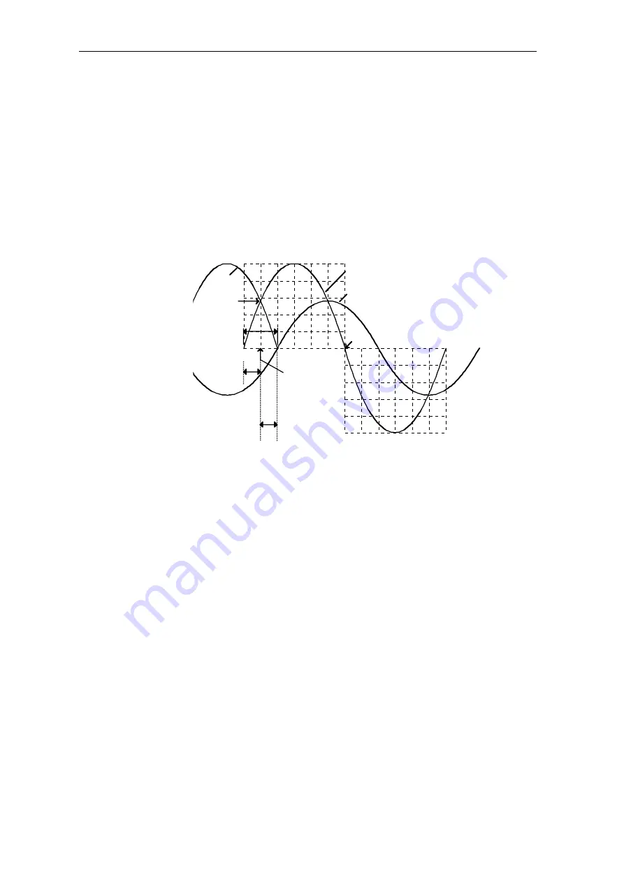
The offset angle PA6.XDA corrects the phase shift between the natural
firing instant of semiconductor device 1 (
α
=0°) and the zero crossover of
the filtered synchronizing voltage (filter on the ITDC). The filter phase
shift is a function of the frequency.
0°
Natural
firing instant,
semiconductor
device 1
-30° offset angle
AVW
Phase voltage L1
Synchronizing voltage , internal
(filtered = phase shift to Vsyn.)
L3
α
=0°
360°
AFI
30°
180°
α
=150°
Fig. 5-5
Schematic representation of the offset angle in the 50[Hz] line supply
The angle 30[°] is specified as a result of the three-phase system.
The FB automatically corrects the existing offset –30[°]. The remaining
deviation should be entered at connection XDA.
e.g.
XDA=0.0
⇒
AVW = -30 [
°
]
XDA=10.0
⇒
AVW = -20 [
°
]
The connections of the power section and electronics section of the
SITOR set must have the same phase position and the clockwise rotating
in order to ensure perfect functioning of the offset angle determination.
(e.g. if the phases are interchanged at the electronics power supply, this
then incorrectly indicates an incorrect offset angle).
The offset angle between line supply voltage L1 and the filtered
synchronizing voltage, which is to be determined when commissioning
the system, should be entered at input PA6.XDA in degrees
(refer to the Section, Determining the offset angle).
Comment


