Setting Hot Standby Pair Parameters
79 of 132
Publication S177E V2.0 Issue 03/05
10 SETTING A HOT STANDBY PAIR PARAMETERS
If the system is a Hot Standby pair then the rack will contain two identical master station PS100
modules, two Power Supplies, PS210, and a Switch module, PS300. In addition it may contain one or
more Ethernet bridges and two PS410 RS232/RS485 converters.
The two master stations must be set to have identical parameters for controlling the loop, and will
usually have identical settings for the communication ports. If a common RS485 highway is used to
communicate with a host then often both the master stations have the same Modbus address. The
information in section 0 above can be used to set up both stations.
Check that the S/W Type is the same on both units of the pair. The software version is reported on the
top diagnostic screen as shown in section 8.7.1.
10.1 Copy Data A to B
The master station is able to copy data from one side to the other as described in section 8.8.3.
Copying only occurs from the Main unit of the pair. If the Modbus address is to be different on the two
master stations (because of the way the host is to be configured) set these according to the host
system requirements, but be careful regarding the “copy to standby settings” in section 8.8.3. The
default condition is to copy tags, address and all parameter data between the two stations.
10.2 Changes to Terminal Connections
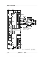
Whenever there is a PS300 Switch module in the rack, and a Hot Standby pair of master stations,
there are connections that must not be made, and some additional connections to make to the rear of
the master station rack.
All the connections are made to one set of terminals only. These are the terminals associated with
master station 'M/S A' - the left hand master station of the pair, viewed from the front of the rack.
The loop connections are made to the 'M/S A' side terminals only.
The ESD input connection is made to the 'M/S A' side terminals only.
DO NOT fit links between Terminal 22 to 23 of either master station.
DO NOT fit links between Terminal 24 to 25 of either master station.
10.2.1 Main/Standby
Connections
It is possible to define whether the left hand (A) or right hand (B) master station will be the unit that
becomes the Main unit and assumes control when both sides are powered on simultaneously. If the
link indicated below is not fitted the unit that powers on first will assume Main status.
On the 'M/S A' terminals only:
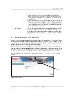
- Link terminal 18 to 19 to select 'M/S B' as the 'Main' unit.
- Or Link terminal 20 to 21 to select 'M/S A' as the 'Main' unit.


