Setting Hot Standby Pair Parameters
81 of 132
Publication S177E V2.0 Issue 12/04
10.3 Hot Standby Parameter Setting and Options
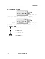
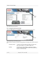
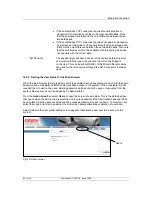
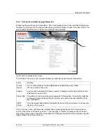
When setting the communication port options, as described in 9.2 above, there is an additional option
on the screen shown in section 8.8.2. With a master station module, in a hot standby pair, it is possible
to set it up to be Active or Passive when in standby mode by pressing button '5'.
The main unit of the pair will always respond to messages it receives on the port. This setting allows
the action of both units when in standby mode to be set. If the setting is made ‘Standby Passive’, the
unit will not respond to most of the messages it receives when it is in standby mode. The exception to
this rule is a message to ‘Change Master’, this will be accepted by a unit in standby mode even if the
port setting is ‘Standby Passive’. (Allowing this one command to be accepted allows a host system
using a direct comms link to the standby unit to make that unit adopt main mode if the link to the main
unit fails.)
If the port is set to ‘Standby Active’ it will always respond to all messages when it is in standby mode.
Both units in the rack must be set to the same value for this parameter – they must never be different.
In most serial comms systems using multi-drop RS485, and in those systems fitted with Ethernet
bridges, the setting will most commonly be ‘Standby Passive’.
However if two independent communication links to the host are used then both stations should be set
to 'Active'. This will ensure that both respond to messages to or from the Host computer. Note that
whatever the setting only the master station that is actually in control of the 2-wire loop will issue
commands to the loop. So with a system using two communication links it is the responsibility of the
Host computer to direct instructions to move valves to the correct master station of the pair.
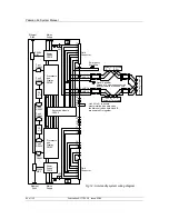
RS485 on A side connected to RS485 on B side, set A and B to Standby Passive
RS485 on A side independent of RS485 on B side, set A and B to Standby Active
Ethernet bridge connecting to both the A side and B side, set A and B to Standby Passive
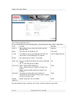
During normal operation it is also possible to change which of the two sides is in control of the loop. In
the Master Station Commands menu, (refer to section 8.5), button '3' allows the master to be changed.
Note that this is only operative on the current 'master' unit of a pair. It can relinquish control and
become the standby unit, making the other master station the 'main'. When commissioning the
system this feature should be checked. The standby LED is lit on the station that is in 'standby' mode.
10.4 The PS300 Keyswitch
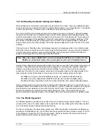
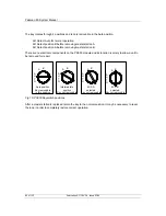
The PS300 keyswitch is located in the centre of the rack, between the two master stations. This unit
is used to force one or the other station to be connected to the loop, allowing the other, disconnected
one, to be safely removed without interrupting the loop.
The Key is removable in the lower Auto position only. When that position is selected both stations are
operating in Hot Standby mode. If a unit fails, then the keyswitch should be moved to select 'A' if 'B' is
to be removed, or moved to 'B' if 'A' is to be removed. The key should not be returned to the 'Auto'
position whilst a master station is removed from the rack.
Note: When one common RS485 link is used connecting the RS485 port on station A to the
RS485 port on station B station, the comms ports must be set to ‘Standby Passive’.

