Pakscan IIE System Manual
50 of 132
Publication S177E V2.0 Issue 03/05
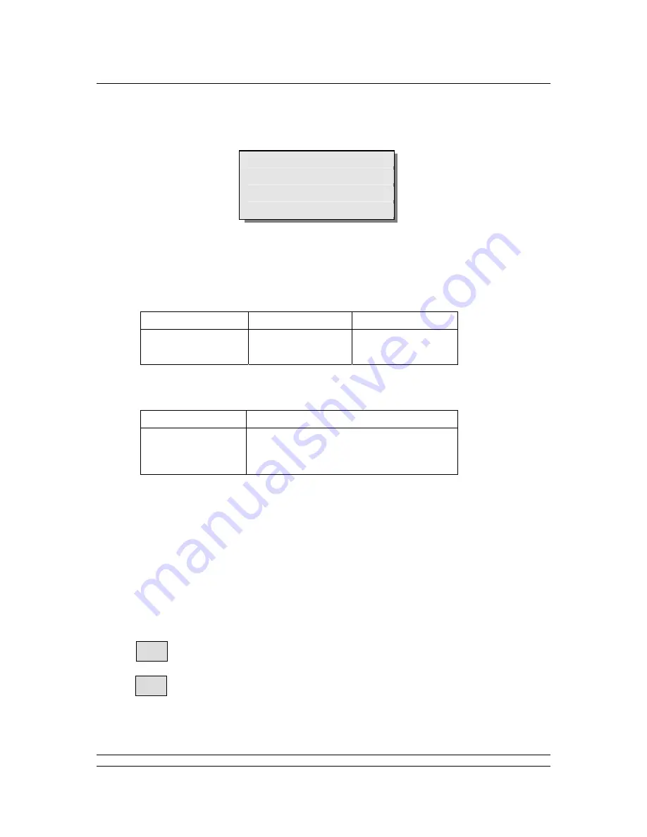
8.7.5
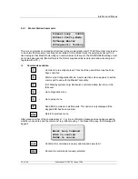
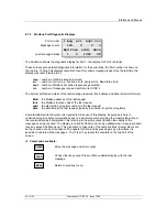
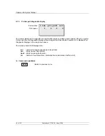
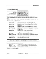
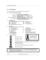
Hot Standby Inter Unit Diagnostic Display
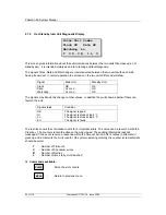
Inter-Unit Comms
Clock OK Data OK
Watchdog Lo
T 0 C 0 R 1 L 0
This screen gives information about the communications between the two units that make up a hot
standby pair. It is intended mainly as an aid to testing and fault diagnosis.
The signals Clock, Data and Watchdog are interconnected between the two units with each side
having its own set. In normal operation the screens on the two units differ and will show:
Signal
Main Unit
Standby Unit
Clock OK OK
Data
Hi or Lo
OK
Watchdog
Hi or Lo
OK
The signals may transiently change to other values. In addition they will show as below if there is a
fault on the unit.
Signal status
Condition
OK
The signal is good
Hi
The signal is stuck at logic ‘1’
Lo
The signal is stuck at logic ‘0’
Err
The signal is faulty
The last line shows the cumulative counts for 4 important errors. The value can be reset to 0 with the
Clear key. The counters record the data on the side viewed. The sending (Main) side resends
messages if it does not receive a response within the Timeout period. After 2 retries (3 attempts) it
gives up and increments the Limit counter. On system operating normally the counter incremental rate
should be small.
T
- Number of Timeouts
C
- Number of Checksum errors
R
- Number of Retries
L
- Number of times retry Limit reached
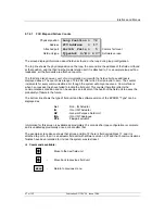
Commands available:
-
Zeros the error counts
-
Return to previous menu
MENU
CLEAR

