Interface and Menus
33 of 132
Publication S177E V2.0 Issue 03/05
8
LOCAL USER INTERFACE
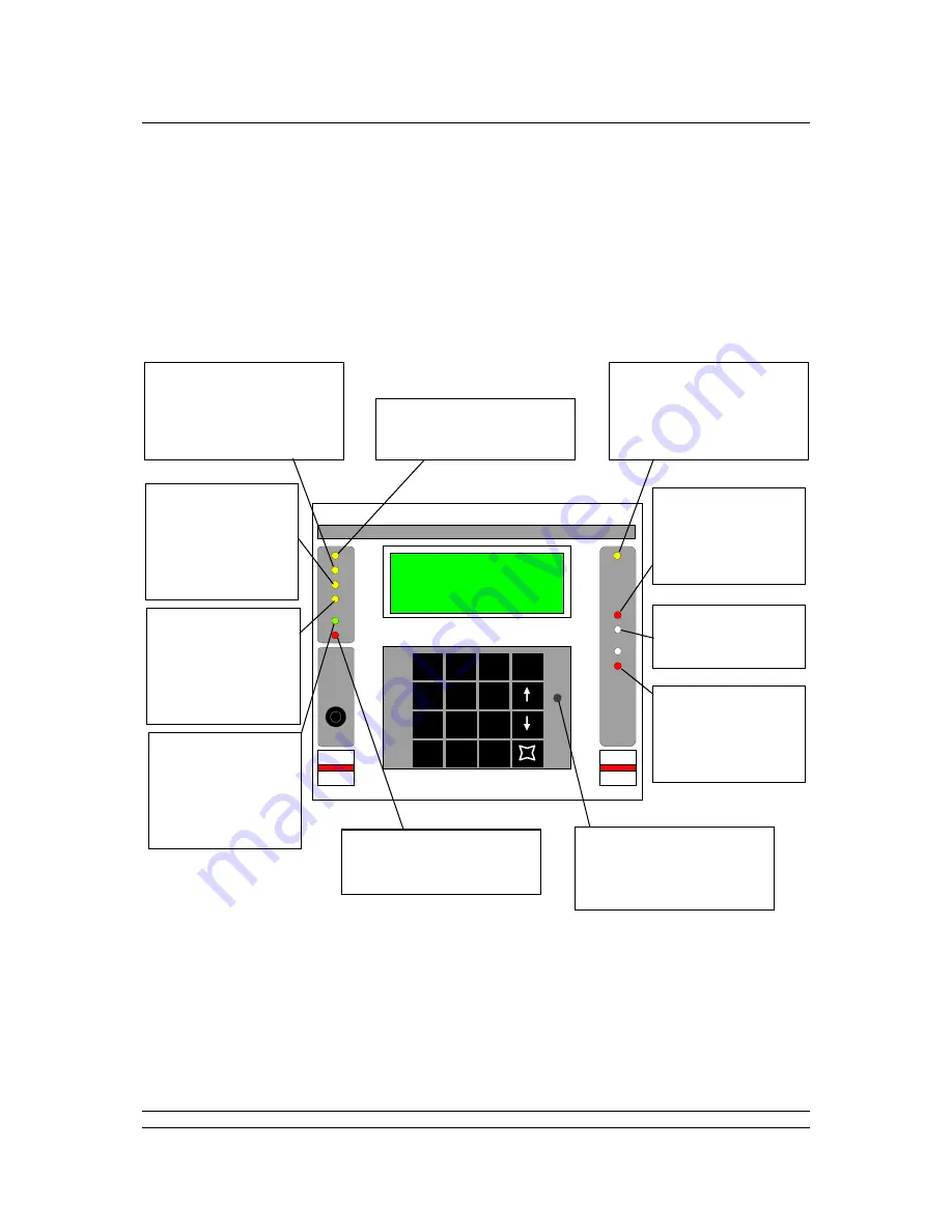
The master station has indication LEDs to show the condition of the hardware and also contains the
main 4 line LCD display and keypad. This section describes the use of this display panel and also the
menu structure for access to the various screens and settings for the system.
8.1 Front Panel Indication LEDs
The Standby Mode LED will only illuminate in a hot standby master station, and then only on the unit
that is currently in standby mode. This can be either the left or right hand PS100 module.
The loop activity indicators flicker as data is transmitted and received, if they both operate together the
loop is complete, but if they alternate then a loop fault exists.
Field
Alarm
New
Alarm
Addr
Fault
Host
Active
Masterstation
Active
Alarm
PS100
PS100
Standby
Port
A
Port
B
Contrast
Menu
1
2
3
6
5
4
7
8
9
0
*
LOAD
CLEAR
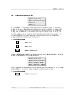
Configuration
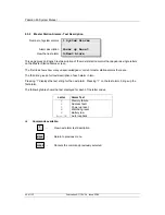
Master MSTAG001
Status=LB Off ESD
9>Alms=P
1>M/S 2>Field Units
Field Alarm (yellow)
Illuminates to indicate that a
field alarm is present
Standby Mode (yellow)
Illuminates when the master
station is forced into standby
by the other master station
of a dual standby pair
Port A (red)
Illuminates to
indicate that current
is flowing into port
A's receiver
Two potentiometers
used during loop
commissioning
Port B (red)
Illuminates to
indicate that current
is flowing into port
B's receiver
LCD Contrast Adjust
Potentiometer
For adjusting the viewing
angle of the LCD screen.
Master Station Alarm (red)
Illuminates when a master
station alarm occurs.
Master Station
Healthy (green)
Illuminates when the
master station
program is running
correctly
Host comms Active
(yellow)
Illuminates to
indicate that data is
on either the RS232
or RS485 highway
Address Fault
(yellow)
Illuminates to
indicate that an
address fault has
occurred.
New Field Alarm (yellow)
Illuminates to indicate that a
new field alarm has
occurred. Cancelled by
accepting an alarm
Fig 11: Master Station Front showing function of LED’s

