Pakscan IIE System Manual
112 of 132
Publication S177E V2.0 Issue 03/05
before the loop fault. The Port A, then Port B LED's, flicker during this stage. Normal scanning of a
broken loop shows up as both LED's flickering, but not together.
Should the setting of field unit parameters have been carried out incorrectly then the system will
identify a field unit that has an address to high or duplicated with another and eliminate these from the
routine data polling. They are marked in the data base as in error and their individual data screen
displays show Comms Failure and Field Unit Fault.
13.4.2 Loop Communications
On a well-behaved loop, the error rate in communications with each field unit should be very low. The
system should be Reconfigured, and once running successfully with no loopbacks present examine
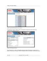
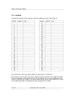
the FCU Map and Failure Counts screen (as shown in section 8.7.4.1).
This screen allows verification that the loop wiring follows the desired pattern. The screen shows both
the physical position on the loop and the address of each field unit that is in communication with the
master station. The screen also reveals a counter recording the number of failures in communications
with each field unit. This counter records every error, including those that do not result in a
communication failure alarm. (The alarm is only generated if the communication fails 3 times in
succession), and it may be set to zero by the ‘Clear’ button.
In most systems communication errors will occur due to interference from associated plant. The main
thing is that they should be relatively infrequent. Examining the counter, waiting a short while, and
comparing the new value with the original is used to monitor the system performance. The counter
only refreshes when the screen is first loaded, so to see changes it is necessary to leave and return to
the selected screen. There should not be a significant change in the error count. If there is a large
difference then it is an indication that there is a problem on the loop. This may be a cable fault (low
resistance to earth for example), or that the loop is being run too fast for the cable fitted, or that a
particular field unit is not functioning correctly.
If line errors cause problems the most likely causes are:
(1)
Twisted pair screen not earthed at master station
(2)
Twisted pair screen earthed at both ends
(3)
Twisted pair screen broken/not linked at field unit(s)
(4)
Line resistance too great
(5)
Line capacitance too great
(6)
Incorrectly adjusted loop voltages
13.4.3 Loop
speed
reprogramming
Problems can occasionally arise during loop speed reprogramming resulting in the loop being left with
field units set at different speeds.
It is possible to recover from this situation by the following procedure:
(1)
Set the desired loop speed to that of the field units that the master station CANNOT talk to.
(2) Re-configure
the
loop
(3)
Re-configure the loop again.

