Technical
Specifications
125 of 132
Publication S177E V2.0 Issue 12/04
16.5.2 Serial Ports
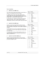
Serial Port 1 (the RS485 port)
Port 1 has a pair of 9-way D-type connectors, one male and one
female. The connections are shown in the table.
The RS485 port has a true tri-state output allowing 2-wire
communications to be used. The master station uses a 2-wire
RS485 highway. If a 4-wire RS485 highway is needed this must
be taken from Port 4 and a PS410 fitted in the rack.
The RTS signal is an output that is asserted when the system
replies to a message. It can be used by RS485 repeaters or
RS485/RS232 converters to switch between transmit and receive.
Serial Port 2 (the RS232 port)
Port 2 is a single 9-way D-type female connector and uses
RS232 hardware protocol. This port can be used as a data port,
or for connection to a serial printer. The connections are shown in
the table.
The CTS signal is an input to the master station that allows an
external device to control the flow of data and is usually needed
by a serial printer.
The master station is set up as DCE equipment, so there is no
need to cross over pins 2 and 3 between the host and master
station on the RS232 link.
Serial Port 3 (the PS410 RS232 port)
Port 3 is a single 9-way D-type female connector and uses
RS232 hardware protocol. This port can be used as a data port
and is also configured as DCE.
Port 1 – RS485
Pin No.
Function
1 NC
2 NC
3 Data
–
4
RTS –
5 Signal
Ground
6 NC
7 NC
8 Data
+
9 RTS
+
Port 2 – RS232
Pin No.
Function
1 NC
2 Receive
3 Transmit
4 NC
5 Signal
Ground
6 NC
7 CTS
8 NC
9 NC
Port 3 – RS232
Pin No.
Function
1 NC
2 Receive
3 Transmit
4 NC
5 Signal
Ground
6 NC
7 NC
8 NC
9 NC

