Setting Parameters
75 of 132
Publication S177E V2.0 Issue 12/04
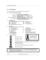
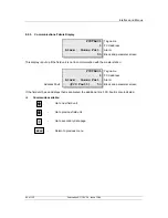
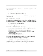
When the settings are correct, press 'MENU' to return to the previous page. The chosen settings will
only become active once you leave the 'set up' screen. Press ‘1’ and then '2' to select Port 2.
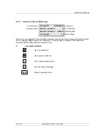
The screen is very similar to the one for Port 1 except that Port 2 can be selected to operate a serial
printer. Make the settings required in the same way as for Port 1.
Having set the port communications parameters it is then necessary to set the alarm linkage if both
comms connections to a single host are being used, or an Ethernet bridge linked to both ports is being
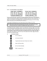
used. Press ‘6’ to gain access to the screen shown in section 8.8.2.1. Linked alarms will operate such
that accepting an alarm using comm port 1 will also cause it to be accepted in the data base serving
comm port 2 (and similarly for comm port 2, it will accept alarms on port 1). If the host system is using
redundant serial communications with two links to one host then the option should be set to ‘Linked’. If
two or more independent hosts are accessing the master station over the serial links then the setting
should be ‘Separate’.
Once the settings are correct, press 'MENU' to install the settings and return to the previous page.
9.3 Loop
Data
In section 7.4 the various pieces of information relating to the loop wiring and the cable parameters
were measured and recorded. When it comes to setting the master station Loop Data the Loop Speed
has to be compatible with that data (also the individual field units must be set to match the master
station setting). The following table indicates the Loop Baud Rate that may be used for various values
of cable resistance and capacitance.
Pakscan Cable Capacitance
Baud Rate
R max
(ohms)
C max for 240 FCU
system
(
µ
F)
C max for 60 FCU
system
(
µ
F)
C max for 20 FCU
system
(
µ
F)
110 500 3.97
4.36
4.45
300 500 1.57
1.98
2.05
600 500 1.02
1.41
1.49
1200 500 0.07
0.47
0.55
2400 500 N/A
0.17
0.25
Each field unit has a capacitance of 2.2nF
The C max figure given is the maximum value for the cable capacitance without the field units
connected.
Note: Never attempt to run the system with cable resistance and capacitance values above
those specified for the chosen baud rate as communication may not be possible.
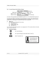
Setup
Loop Speed
110, 300, 600, 1200 or 2400 baud
Number of FCU’s
In the range 1 to 240
Doubling
On or Off


