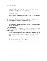
Jumpers and Links
23 of 132
Publication S177E V2.0 Issue 03/05
6
INITIAL SETTING UP
The factory default settings for the jumpers and links inside the master station will be satisfactory for
most applications. However there are some cases where special settings could be required. Before
applying any power to the master station check that the internal settings of the jumpers match the
system requirements. These jumpers will have been factory set to the default positions, or to user
specified positions, prior to dispatch.
In addition to the internal jumpers there may be a need to fit external links to achieve satisfactory
operation of the installed unit, for example with Hot Standby units. These links can be fitted prior to
installation.
6.1 Jumper
Settings
The PS100 CPU and Display module contains a number of jumpers to set some of the parameters for
the performance of the unit. These are factory set and should generally not require adjustment at any
time. However there are links that may need to be fitted to match specific applications. There are no
jumper links on the power board, display board or loop driver board that require customer adjustment.
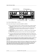
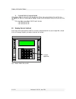
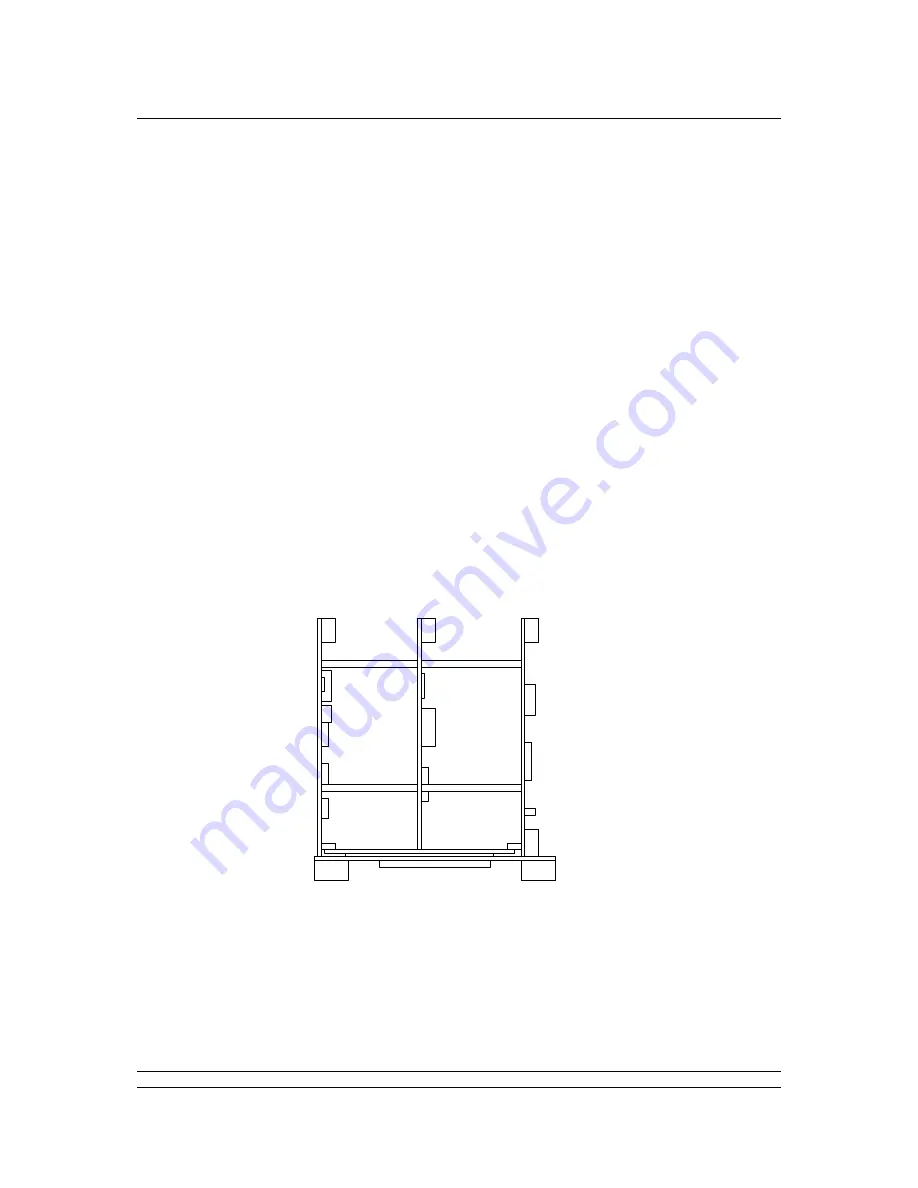
The diagram Fig. 5 is a top view of the PS100 module showing the different circuit boards. Fig. 6
shows the layout of the V25 card of the module. This is the PCB located to the left of the display
screen when viewed from the front; it is clearly distinguished by the battery on the board.
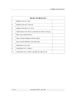
The function and default settings of the jumpers is listed in the table, please note that some select the
type of integrated circuit used, and therefore may vary from one unit to another.
Front Display
V25 CPU
board
Loop Driver
board
Power
board
Display
board
Rear Connectors
Fig 5: The PS100 card positions

