Pakscan IIE System Manual
30 of 132
Publication S177E V2.0 Issue 03/05
2. Measure, and note down, the resistance of each core (the core connected to A and B will
have a higher resistance than the core connected to the common).
3. Check the resistance between the cores, this should be a high resistance as they are not
connected together. (Note that if a field unit has power to it, then the internal circuitry will
connect the two cores together.)
4. Join the 2 wires that will be connected to Port B together and measure the total resistance of
the whole loop cable - note this down as you will need it for reference later.
7.4.2 Screen
Continuity
With the Port B cables still connected together make sure that the screen is isolated from the loop
cores themselves, there should be a high resistance between screen and cores.
5. Check the screen is continuous by measuring the resistance of the screen between the two
ends.
6. Check that the screen is isolated from earth by measuring the resistance between the screen
and your screen earth point.
7.4.3 Cable
Capacitance
The capacitance between the cores, and to the screen, is critical to the system performance. Too high
a capacitance for the selected loop baud rate will result in poor communications, or even
communication failure.
7. Disconnect the join between the 2 cores that connect to Port B, the cores and screen are now
all separated.
8. With the digital meter set to capacitance, measure the core to core capacitance, and note it
down.
9. Also measure the core to screen capacitance, which will probably be slightly higher, for cable
core 1.
10. Measure the capacitance between core 2 and the screen.
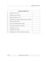
If any problems are encountered during these tests rectify them before proceeding. The results should
be noted on a form such as that shown overleaf.

