358
Interpreting LED Codes
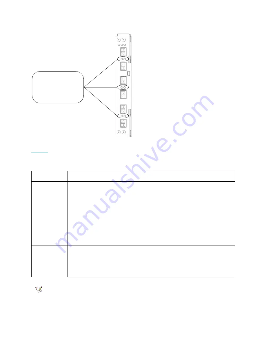
Figure 44
Locations and Colors of I/O Blade Fibre Port Link LEDs
describes how to interpret the link LED activity that you might see. There are two different models
of I/O blade: 6404 and 7404. LED behavior varies based on which model is installed in the library.
Table 23
Explanations of I/O Blade Link LED States
Blade Model
Possible Green LED States and Explanations
6404
• Solid on — the I/O blade has established a proper link and is ready to use. The
blade FC port detects light through the fiber optic cable.
• Blinks slowly — the link is up and currently transporting commands.
• Blinks rapidly — when the I/O blade is beginning to reboot or power up, all I/O blade
link LEDs, along with the I/O blade’s green status LED, blink rapidly to indicate that
the blade is starting the Power On Self Test (POST).
• Blinks with other link LEDs in a racetrack pattern — when all of the I/O blade link
LEDs blink consecutively in a clockwise order, the blade is booting up. This pattern
stops when the blade is powered and ready. If the pattern doesn’t stop, the blade
is unable to completely boot up. In this situation, follow the repair page instructions.
• Solid off — the I/O blade does not detect light through the fiber optic cable.
7404
• Solid on — the I/O blade has established a link but is not currently transporting
data.
• Blinks — the link is active and is currently transporting data.
• Solid off — the I/O blade has not established a link
OR
the link is active and is
currently transporting a large amount of data.
Note
For the 7404 I/O blade, fibre port LEDs are off while the blade is booting up.
FC I/O blade link LEDs
- left = green (belongs
to port below)
- right = green (belongs
to port above)
Summary of Contents for Scalar i6000
Page 20: ...8 About This Guide and Your Product...
Page 38: ...26 Installing a Stand Alone Control Module...
Page 104: ...92 Installing a Multi Module Library...
Page 156: ...144 Installing Cartridges...
Page 164: ...152 Setting up Your Library for Access...
Page 242: ...230 Configuring the Library...
Page 304: ...292 Adding Optional Hardware eight 2 5 mm screws...
Page 318: ...306 Adding Optional Hardware...
Page 336: ...324 Installation Testing and Verification Figure 35 Example Test Log Output...
Page 356: ...344 Testing and Calibrating the Digital Level...
Page 362: ...350 LBX Board and Terminator...
Page 380: ...368 Glossary...
Page 384: ...372 Index...


