6–42
Replacement Procedures
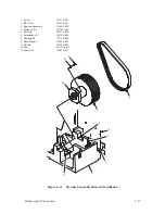
Magnetic Pickup Unit
(Figure 6–13)
Removal
1. Disconnect the AC power cord from the rear of the printer. Open the top
cover.
2. Remove the right side panel as described on page 6–4.
3. Loosen two captive screws and remove the cam cover (not shown).
4. Disconnect Magnetic Pickup Unit connector P35 (1).
5. Loosen the MPU clamping screw (2). Unscrew the MPU (3) from the
MPU arm (4) and remove it from the printer.
Installation
1. Screw the MPU into the MPU arm until it is about half a turn from the
flywheel assembly (5).
2. Connect MPU connector P35.
3. Perform the MPU gap and phasing adjustments as described on pages
5–20 and 5–22 of Chapter 5, Alignments and Adjustments.
4. Install the cam cover and tighten two captive screws.
5. Install the right side panel as described on page 6–4.
6. Close the top cover.
Summary of Contents for P9012
Page 1: ...P N 132305 001 Rev E P9012 Multifunction Line Printer...
Page 49: ...2 31 Principles of Operation Power Supply PCBAs 1 3 SHORT OPEN Figure 2 21 Power Supply PCBA...
Page 58: ...2 40 Principles of Operation...
Page 84: ...4 18 Troubleshooting...
Page 118: ...5 34 Alignments and Adjustments...
Page 203: ...6 85 Replacement Procedures This page intentionally left blank...
Page 214: ...6 96 Replacement Procedures...
Page 236: ...A 22 Power Paper Stacker Maintenance...
Page 246: ...D 2 Torque Table...
Page 254: ...Index 6...
Page 255: ......
Page 256: ...132305 001 Rev E...


