6–15
Replacement Procedures
1
2
3
5
6
9 (under)
4
7
8
12
13
14
10
11
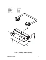
NOTE: Only one motor shown.
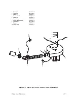
1. Hub Screw
103677–009
2. Hub
102526–001
3. Motor, Ribbon Drive
131306–001
4. Screw
102786–605
5. Washer
101526–002
6. Cover
131694–001
7. Ribbon Deck Assembly
131883–903
8. Motor Cable Connector
Part of item 3
9. Ribbon Control PCBA
132335–901
10. Screw (2)
101513–016
11. Washer (2)
140090–001
12. Shaft Wick
132322–001
13. Reservoir Wick
132321–001
14. Shaft Seal
140632–001
Figure 6–5. Ribbon Drive Motor Removal/Installation
Summary of Contents for P9012
Page 1: ...P N 132305 001 Rev E P9012 Multifunction Line Printer...
Page 49: ...2 31 Principles of Operation Power Supply PCBAs 1 3 SHORT OPEN Figure 2 21 Power Supply PCBA...
Page 58: ...2 40 Principles of Operation...
Page 84: ...4 18 Troubleshooting...
Page 118: ...5 34 Alignments and Adjustments...
Page 203: ...6 85 Replacement Procedures This page intentionally left blank...
Page 214: ...6 96 Replacement Procedures...
Page 236: ...A 22 Power Paper Stacker Maintenance...
Page 246: ...D 2 Torque Table...
Page 254: ...Index 6...
Page 255: ......
Page 256: ...132305 001 Rev E...


