6–30
Replacement Procedures
Installation
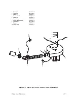
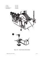
1. Position the coil over the pole pins and push straight down. The pins
should protrude slightly through the coil.
2. Install the coil clamp plate, two screws (8), and washers (9). Make sure
that the coil leads do not overlap each other under the clamp, and that the
red and white leads are installed in their original positions.
3. Route the coil leads under the coil lead clamp. Install the two clamp
screws (5), but do not tighten.
4. Install the leads into the coil connector. Make sure the sense of color
coding is identical with other coils, and the terminals are locked in.
CAUTION
Make sure the leads lie at least 3/16 inch from the clamp screws before
tightening the screws. Do not overtighten. Damage to leads, coils, or
hammer drivers is possible.
5. Adjust the path of the leads so that the service loop matches that of other
leads. Tighten two clamp screws (5).
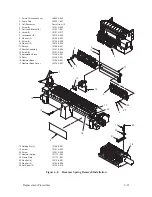
6. Install the hammer spring as described on page 6–24.
Summary of Contents for P9012
Page 1: ...P N 132305 001 Rev E P9012 Multifunction Line Printer...
Page 49: ...2 31 Principles of Operation Power Supply PCBAs 1 3 SHORT OPEN Figure 2 21 Power Supply PCBA...
Page 58: ...2 40 Principles of Operation...
Page 84: ...4 18 Troubleshooting...
Page 118: ...5 34 Alignments and Adjustments...
Page 203: ...6 85 Replacement Procedures This page intentionally left blank...
Page 214: ...6 96 Replacement Procedures...
Page 236: ...A 22 Power Paper Stacker Maintenance...
Page 246: ...D 2 Torque Table...
Page 254: ...Index 6...
Page 255: ......
Page 256: ...132305 001 Rev E...


