6–26
Replacement Procedures
e.
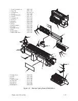
Place the shroud on the shuttle assembly. Install two screws (9) and
washers (10) at the top loosely.
f.
Install two screws (6), lockwashers (7), and washers (8) loosely. Pull
the shroud toward the front of the printer and tighten the top screws
(9). Release the shroud, then tighten the front screws (6).
IMPORTANT
It is very important that steps (e) and (f) are followed to prevent wear on
the front of the shroud. Incorrect placement can also cause poor print
quality. Inspect the front area of the shroud to ensure that there is
adequate clearance between the shroud and the screws on the hammer
bank assembly.
g. Install two coil lead brackets to the shroud with four screws (4) and
eight washers (23, 24). Be sure to position the brackets down against
the ledge on the shroud. Working from left to right, connect the coil
connectors and reinstall the velcro pad.
4. Install the ribbon deck assembly as described on page 6–8.
Summary of Contents for P9012
Page 1: ...P N 132305 001 Rev E P9012 Multifunction Line Printer...
Page 49: ...2 31 Principles of Operation Power Supply PCBAs 1 3 SHORT OPEN Figure 2 21 Power Supply PCBA...
Page 58: ...2 40 Principles of Operation...
Page 84: ...4 18 Troubleshooting...
Page 118: ...5 34 Alignments and Adjustments...
Page 203: ...6 85 Replacement Procedures This page intentionally left blank...
Page 214: ...6 96 Replacement Procedures...
Page 236: ...A 22 Power Paper Stacker Maintenance...
Page 246: ...D 2 Torque Table...
Page 254: ...Index 6...
Page 255: ......
Page 256: ...132305 001 Rev E...


