6–21
Replacement Procedures
1
2
3
4
7
8
9
11
5
6
10
12
15
16
13
14
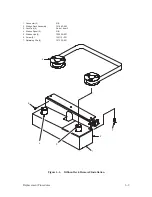
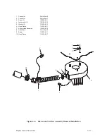
1. Forms Thickness Lever
108652–002
2. Screw (2)
103258–001
3. Cam Cover
140269–001
4. Screw (6)
140113–001
5. Front Cover Plate
131580–001
6. Gasket
131492–001
7. Screw (2)
101541–057
8. Lockwasher (2)
102158–001
9. Dust Barrier Block
133442–001
10. Coil Connector
Part of item 15
11. Screw (2)
101514–009
12. Lockwasher (2)
102158–007
13. Shoulder Screw
109729–001
14. Lockwasher
102158–008
15. Shuttle Assembly
131419–904
16. Alignment Pin
N/A
Figure 6–7. Shuttle Assembly Removal/Installation
Summary of Contents for P9012
Page 1: ...P N 132305 001 Rev E P9012 Multifunction Line Printer...
Page 49: ...2 31 Principles of Operation Power Supply PCBAs 1 3 SHORT OPEN Figure 2 21 Power Supply PCBA...
Page 58: ...2 40 Principles of Operation...
Page 84: ...4 18 Troubleshooting...
Page 118: ...5 34 Alignments and Adjustments...
Page 203: ...6 85 Replacement Procedures This page intentionally left blank...
Page 214: ...6 96 Replacement Procedures...
Page 236: ...A 22 Power Paper Stacker Maintenance...
Page 246: ...D 2 Torque Table...
Page 254: ...Index 6...
Page 255: ......
Page 256: ...132305 001 Rev E...

