6–72
Replacement Procedures
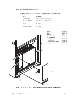
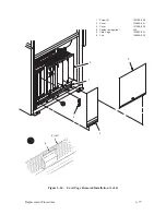
DCU, MCU, Mechanism Driver PCBAs
(Figure 6–24)
Removal
NOTE: The DCU, MCU, and Mechanism Driver PCBA locations are
labeled at the top of the card cage. Removal/installation is the same
for all cards. The DCU PCBA is illustrated.
1. Remove the right side panel as described on page 6–4.
2. Loosen two screws (1) and remove the cover (2).
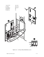
3. On the DCU only, disconnect two connectors (3).
4. Lift ejection levers (4) and slide the PCBA (5) out of the card cage (6).
Installation
1. If installing a new PCBA:
a.
Compare the original PCBA with the replacement. If the new board
is a different firmware version, refer to the P9012 User’s Manual for
configuration details.
b. If the new board is the same firmware version, remove any PROMs,
jumpers, or terminations from the original board and install them on
the replacement board. (For PROM locations, refer to page 6–73.)
CAUTION
Installing a PCBA in the wrong slot will damage the PCBA and
connector.
2. Slide the PCBA into the correct slot in the card cage with the component
side on the right. Engage the ejection levers at the edge of the card cage
and close to seat the PCBA.
3. On the DCU only, connect two connectors.
4. Install the cover and tighten two screws.
5. Install the right side panel as described on page 6–4.
Summary of Contents for P9012
Page 1: ...P N 132305 001 Rev E P9012 Multifunction Line Printer...
Page 49: ...2 31 Principles of Operation Power Supply PCBAs 1 3 SHORT OPEN Figure 2 21 Power Supply PCBA...
Page 58: ...2 40 Principles of Operation...
Page 84: ...4 18 Troubleshooting...
Page 118: ...5 34 Alignments and Adjustments...
Page 203: ...6 85 Replacement Procedures This page intentionally left blank...
Page 214: ...6 96 Replacement Procedures...
Page 236: ...A 22 Power Paper Stacker Maintenance...
Page 246: ...D 2 Torque Table...
Page 254: ...Index 6...
Page 255: ......
Page 256: ...132305 001 Rev E...

