5–2
Alignments and Adjustments
Alignments and Adjustments
This chapter contains the alignment and adjustment procedures done at
the field service maintenance level.
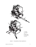
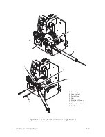
Ribbon Tracking Check and Adjustment
(Figure 5–1)
1. Make sure paper is loaded in the printer and a full ribbon spool is on the
right. Turn power on and open the printer top cover.
2. Set the forms thickness adjustment lever (1) to any position between “A”
and “B.” Make sure no error indications appear.
3. Refer to the P9012 User’s Manual and command a shuttle/ribbon
self–test. Shuttle action and ribbon motion should begin.
4. On either the left or right ribbon guide (2), momentarily short across the
skids (3).
5. Let the ribbon run completely out of the spool. Verify the ribbon is
centered in the guide. If not, follow these steps:
a.
Loosen two screws (4) with washers (5) until the left ribbon guide
can be rotated about the guide post (6).
b. Pivot the guide until the ribbon tracks in the center.
c.
Tighten two screws.
d. Verify that the ribbon is centered and winds up without interference
on the left spool.
6. The spool should automatically reverse. If it does not, follow these steps:
a.
Replace the ribbon (page 6–8). Rerun the test.
b. If there is still an error, check the cabling.
c.
If ribbon tracking is still unsuccessful, replace the ribbon deck
assembly (page 6–8).
Summary of Contents for P9012
Page 1: ...P N 132305 001 Rev E P9012 Multifunction Line Printer...
Page 49: ...2 31 Principles of Operation Power Supply PCBAs 1 3 SHORT OPEN Figure 2 21 Power Supply PCBA...
Page 58: ...2 40 Principles of Operation...
Page 84: ...4 18 Troubleshooting...
Page 118: ...5 34 Alignments and Adjustments...
Page 203: ...6 85 Replacement Procedures This page intentionally left blank...
Page 214: ...6 96 Replacement Procedures...
Page 236: ...A 22 Power Paper Stacker Maintenance...
Page 246: ...D 2 Torque Table...
Page 254: ...Index 6...
Page 255: ......
Page 256: ...132305 001 Rev E...


