6–95
Replacement Procedures
11
1
3
6
2
4
5
9
7
10
8
8
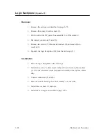
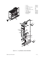
1. Nut (3)
101525–012
2. Washer (3)
140858–001
3. DC Power Bus Assembly
131313–001
4. Stud (3)
N/A
5. Connector (Fans)
N/A
6. Connector (Hammer Driver)
N/A
7. Screw (10)
102559–606
8. Metal Washer (3)
101526–002
9. Nylon Washer (7)
101547–011
10. Logic Backplane
133453–001
11. Card Cage
133610–001
Figure 6–31. Logic Backplane Removal/Installation
Summary of Contents for P9012
Page 1: ...P N 132305 001 Rev E P9012 Multifunction Line Printer...
Page 49: ...2 31 Principles of Operation Power Supply PCBAs 1 3 SHORT OPEN Figure 2 21 Power Supply PCBA...
Page 58: ...2 40 Principles of Operation...
Page 84: ...4 18 Troubleshooting...
Page 118: ...5 34 Alignments and Adjustments...
Page 203: ...6 85 Replacement Procedures This page intentionally left blank...
Page 214: ...6 96 Replacement Procedures...
Page 236: ...A 22 Power Paper Stacker Maintenance...
Page 246: ...D 2 Torque Table...
Page 254: ...Index 6...
Page 255: ......
Page 256: ...132305 001 Rev E...


