6–18
Replacement Procedures
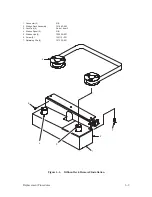
Shuttle Assembly
(Figure 6–7)
Removal
1. Disconnect the AC power cord from the rear of the printer. Open the top
cover.
2. Remove the ribbon deck assembly as described on page 6–8.
3. Set the forms thickness lever (1) to fully open. Remove paper.
4. Loosen two captive screws (2) and remove the cam cover (3).
5. Remove six screws (4), the cam front cover plate (5), and the gasket (6).
6. Remove two screws (7), lockwashers (8), and the dust barrier block (9).
7. Disconnect the coil connectors (10).
8. Remove two screws (11), lockwashers (12), and one shoulder screw (13)
and lockwasher (14).
9. Swing the left end of the shuttle assembly (15) toward the front of the
printer to relieve the shuttle spring preload. Then, lift the shuttle
assembly off the alignment pin (16).
Summary of Contents for P9012
Page 1: ...P N 132305 001 Rev E P9012 Multifunction Line Printer...
Page 49: ...2 31 Principles of Operation Power Supply PCBAs 1 3 SHORT OPEN Figure 2 21 Power Supply PCBA...
Page 58: ...2 40 Principles of Operation...
Page 84: ...4 18 Troubleshooting...
Page 118: ...5 34 Alignments and Adjustments...
Page 203: ...6 85 Replacement Procedures This page intentionally left blank...
Page 214: ...6 96 Replacement Procedures...
Page 236: ...A 22 Power Paper Stacker Maintenance...
Page 246: ...D 2 Torque Table...
Page 254: ...Index 6...
Page 255: ......
Page 256: ...132305 001 Rev E...


