5–12
Alignments and Adjustments
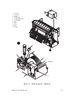
7. Install a counterweight spring shim as follows:
NOTE: More than one shim may be required to obtain the desired effect.
a.
Loosen screw (9) about three turns.
b. With the screwdriver, press in on the loosened screw to create space
for a shim (10).
c.
Install a shim between the spring spacer and the casting (11).
d. Tighten the screw.
8. Operate the printer.
a.
Run the printer for 10 minutes using a shuttle/ribbon fast test. Check
for rattle and increase the preload if necessary.
b. Run the printer using a shuttle/ribbon slow test. Check for stalls or
no–start conditions and decrease the preload if necessary.
9. Install the cam cover and the attached gasket.
10. Tighten two screws and close the printer cover.
Summary of Contents for P9012
Page 1: ...P N 132305 001 Rev E P9012 Multifunction Line Printer...
Page 49: ...2 31 Principles of Operation Power Supply PCBAs 1 3 SHORT OPEN Figure 2 21 Power Supply PCBA...
Page 58: ...2 40 Principles of Operation...
Page 84: ...4 18 Troubleshooting...
Page 118: ...5 34 Alignments and Adjustments...
Page 203: ...6 85 Replacement Procedures This page intentionally left blank...
Page 214: ...6 96 Replacement Procedures...
Page 236: ...A 22 Power Paper Stacker Maintenance...
Page 246: ...D 2 Torque Table...
Page 254: ...Index 6...
Page 255: ......
Page 256: ...132305 001 Rev E...


