6–76
Replacement Procedures
Card Cage
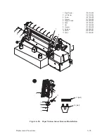
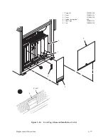
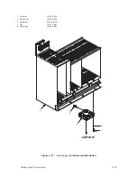
(Figure 6–26)
Removal
1. Disconnect the AC power cord from the rear of the printer.
2. Remove the right side panel as described on page 6–4.
3. Loosen the four screws (1) which secure the two card cage covers (2, 3).
Do not remove the screws. Remove the card cage covers by sliding them
up and out.
4. Disconnect the cables (4) from the PCBAs in the card cage (5).
Disengage the cables from the clips (6) mounted along the bottom edge
of the card cage.
(continued on page 6–78)
Summary of Contents for P9012
Page 1: ...P N 132305 001 Rev E P9012 Multifunction Line Printer...
Page 49: ...2 31 Principles of Operation Power Supply PCBAs 1 3 SHORT OPEN Figure 2 21 Power Supply PCBA...
Page 58: ...2 40 Principles of Operation...
Page 84: ...4 18 Troubleshooting...
Page 118: ...5 34 Alignments and Adjustments...
Page 203: ...6 85 Replacement Procedures This page intentionally left blank...
Page 214: ...6 96 Replacement Procedures...
Page 236: ...A 22 Power Paper Stacker Maintenance...
Page 246: ...D 2 Torque Table...
Page 254: ...Index 6...
Page 255: ......
Page 256: ...132305 001 Rev E...


