6–17
Replacement Procedures
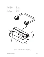
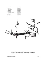
1. Connector
Part of item 9
2. Connector
Part of item 7
3. Screw (3)
102998–001
4. Lockwasher (3)
102158–002
5. Washer (3)
101526–003
6. Hose Clamp
141532–001
7. Airflow Hose Assembly
133445–902
8. Outlet Boot
Part of item 9
9. Blower
131907–901
10. Hose Clamp
141532–001
1
3
4
5
9
2
8
6
7
10
Figure 6–6. Blower and Airflow Assembly Removal/Installation
Summary of Contents for P9012
Page 1: ...P N 132305 001 Rev E P9012 Multifunction Line Printer...
Page 49: ...2 31 Principles of Operation Power Supply PCBAs 1 3 SHORT OPEN Figure 2 21 Power Supply PCBA...
Page 58: ...2 40 Principles of Operation...
Page 84: ...4 18 Troubleshooting...
Page 118: ...5 34 Alignments and Adjustments...
Page 203: ...6 85 Replacement Procedures This page intentionally left blank...
Page 214: ...6 96 Replacement Procedures...
Page 236: ...A 22 Power Paper Stacker Maintenance...
Page 246: ...D 2 Torque Table...
Page 254: ...Index 6...
Page 255: ......
Page 256: ...132305 001 Rev E...


