6–32
Replacement Procedures
Counterweight Assembly
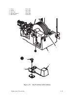
(Figure 6–10)
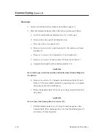
Removal
1. Disconnect the AC power cord from the rear of the printer. Open the top
cover.
2. Remove the right side panel as described on page 6–4.
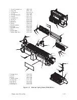
3. Loosen two captive screws (1) and remove the cam cover (2).
4. Remove six screws (3), the cam front cover plate (4) and the gasket (5).
5. Loosen one screw (11) about three turns, but DO NOT remove it at this
time.
6. Using a hex–tipped screwdriver, push on screw (11) to relieve the spring
force on the shim(s) (10). Remove the shim(s) to eliminate the
counterweight preload.
7. Remove one screw (11), lockwasher (9), and washer (12).
8. Remove three screws (6), lockwashers (7), and washers (8).
9. Move the counterweight (13) away from the cam (14); slide it forward
past the cam. The spring (15) and spring seats (16) will come free.
Summary of Contents for P9012
Page 1: ...P N 132305 001 Rev E P9012 Multifunction Line Printer...
Page 49: ...2 31 Principles of Operation Power Supply PCBAs 1 3 SHORT OPEN Figure 2 21 Power Supply PCBA...
Page 58: ...2 40 Principles of Operation...
Page 84: ...4 18 Troubleshooting...
Page 118: ...5 34 Alignments and Adjustments...
Page 203: ...6 85 Replacement Procedures This page intentionally left blank...
Page 214: ...6 96 Replacement Procedures...
Page 236: ...A 22 Power Paper Stacker Maintenance...
Page 246: ...D 2 Torque Table...
Page 254: ...Index 6...
Page 255: ......
Page 256: ...132305 001 Rev E...


