5–24
Alignments and Adjustments
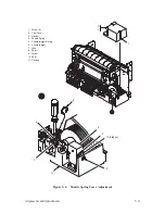
Shuttle Belt Tension
(Figure 5–10)
Tension Check
1. Remove the right side panel as described on page 6–4 of Chapter 6,
Replacement Procedures.
2. Loosen the two captive screws and remove the cam cover (1).
3. Observe the shuttle belt (2) and press down with your finger in the
middle using about
±
2 oz. of force.
4. If the belt deflection is significantly more or less than 0.21 inches (5.3
mm), perform the adjustment procedure below.
Adjustment
1. Loosen the four nuts (3).
2. Position the motor (4) to obtain the proper belt tension. Do not allow the
motor to tilt.
3. Tighten the four nuts.
4. Return the printer to normal operation.
Summary of Contents for P9012
Page 1: ...P N 132305 001 Rev E P9012 Multifunction Line Printer...
Page 49: ...2 31 Principles of Operation Power Supply PCBAs 1 3 SHORT OPEN Figure 2 21 Power Supply PCBA...
Page 58: ...2 40 Principles of Operation...
Page 84: ...4 18 Troubleshooting...
Page 118: ...5 34 Alignments and Adjustments...
Page 203: ...6 85 Replacement Procedures This page intentionally left blank...
Page 214: ...6 96 Replacement Procedures...
Page 236: ...A 22 Power Paper Stacker Maintenance...
Page 246: ...D 2 Torque Table...
Page 254: ...Index 6...
Page 255: ......
Page 256: ...132305 001 Rev E...


