6–10
Replacement Procedures
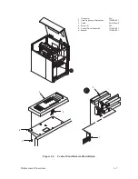
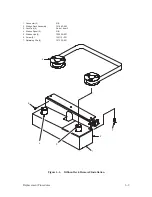
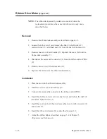
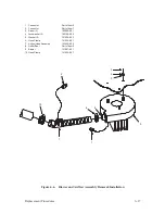
Ribbon Control PCBA
(Figure 6–4)
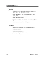
Removal
1. Remove the ribbon deck assembly as described on page 6–8.
2. Remove two screws (1) and washers (2) from the ribbon deck covers (3).
3. Remove two ribbon deck covers from the ribbon deck housing (4).
4. Disconnect connector J45 (5) from shunt plug P45 (6).
5. Disconnect connectors (7) and (8) from PCBA connectors RMJ1 (9) and
RGJ1 (10).
6. Disconnect connectors (11) and (12) from PCBA connectors RMJ2 (13)
and RGJ2 (14).
7. Disengage connectors J30 (15) and J33 (16) from the ribbon deck
housing.
8. Remove four hex head screws (17) and flat washers (18).
9. Remove the ribbon control PCBA (19) from the ribbon deck housing.
Summary of Contents for P9012
Page 1: ...P N 132305 001 Rev E P9012 Multifunction Line Printer...
Page 49: ...2 31 Principles of Operation Power Supply PCBAs 1 3 SHORT OPEN Figure 2 21 Power Supply PCBA...
Page 58: ...2 40 Principles of Operation...
Page 84: ...4 18 Troubleshooting...
Page 118: ...5 34 Alignments and Adjustments...
Page 203: ...6 85 Replacement Procedures This page intentionally left blank...
Page 214: ...6 96 Replacement Procedures...
Page 236: ...A 22 Power Paper Stacker Maintenance...
Page 246: ...D 2 Torque Table...
Page 254: ...Index 6...
Page 255: ......
Page 256: ...132305 001 Rev E...


