2–9
Principles of Operation
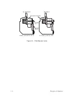
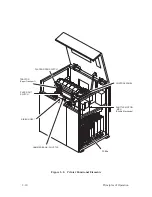
Printer Functional Elements
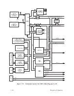
(Figure 2–8 and Figure 2–9)
The printer is made up of the following functional elements:
•
Control Panel
•
Data Control Unit (DCU) PCBA
•
Mechanism Control Unit (MCU) PCBA
•
Mechanism Driver PCBA
•
Hammer Driver PCBA(s)
•
Hammer Bank and Shuttle Mechanics/Magnetic Pickup (MPU)
•
Power Supply PCBA(s)
•
Ribbon Deck
•
Paper Transport
•
Platen Open/Paper Out Switches
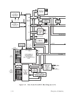
Figure 2–8 shows the basic interrelation of these elements and Figure 2–9 is
a simplified block diagram of the printer.
Summary of Contents for P9012
Page 1: ...P N 132305 001 Rev E P9012 Multifunction Line Printer...
Page 49: ...2 31 Principles of Operation Power Supply PCBAs 1 3 SHORT OPEN Figure 2 21 Power Supply PCBA...
Page 58: ...2 40 Principles of Operation...
Page 84: ...4 18 Troubleshooting...
Page 118: ...5 34 Alignments and Adjustments...
Page 203: ...6 85 Replacement Procedures This page intentionally left blank...
Page 214: ...6 96 Replacement Procedures...
Page 236: ...A 22 Power Paper Stacker Maintenance...
Page 246: ...D 2 Torque Table...
Page 254: ...Index 6...
Page 255: ......
Page 256: ...132305 001 Rev E...


