5–28
Alignments and Adjustments
Paper Motion Sensor
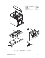
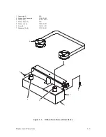
(Figure 5–12)
Test
1. Verify that the printer configuration is set to enable the paper motion
sensor (see the P9012 User’s Manual).
2. Load paper and run several top–of–form operations.
3. Refer to the P9012 User’s Manual and command a self test and run
several pages. Watch for error messages.
4. If no error messages occur in steps 2 and 3, go to the next step. If an
error message displays, follow the steps in “Position Check.”
5. Tear off a 2–inch section of paper including the holes from the edge of
the paper below the left tractor. Advance the torn section of the paper
through the tractor. An error message should appear. This indicates the
paper motion circuitry is functioning properly.
6. If an error message does not display, follow the steps in the next section.
NOTE: You can follow the steps below or you can order a left tractor that
already has an aligned sensor.
Position Check
1. Open the printer cover.
2. Remove paper from the printer.
3. Open the gate of the left tractor (1) and inspect the sensor (5).
4. If both apertures are visible, unobscured, and centered beneath the tractor
pins, the sensor position is correct.
Summary of Contents for P9012
Page 1: ...P N 132305 001 Rev E P9012 Multifunction Line Printer...
Page 49: ...2 31 Principles of Operation Power Supply PCBAs 1 3 SHORT OPEN Figure 2 21 Power Supply PCBA...
Page 58: ...2 40 Principles of Operation...
Page 84: ...4 18 Troubleshooting...
Page 118: ...5 34 Alignments and Adjustments...
Page 203: ...6 85 Replacement Procedures This page intentionally left blank...
Page 214: ...6 96 Replacement Procedures...
Page 236: ...A 22 Power Paper Stacker Maintenance...
Page 246: ...D 2 Torque Table...
Page 254: ...Index 6...
Page 255: ......
Page 256: ...132305 001 Rev E...

