6–28
Replacement Procedures
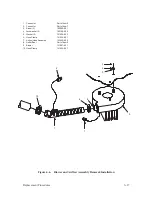
Hammer Coil
(Figure 6–9)
Removal
1. Remove the hammer spring at the faulty coil location as described on
page 6–22.
2. Carefully separate the two coil leads (1) from the connector (2) as
follows:
CAUTION
Do not move the connector releasing tabs any more than necessary to
remove the leads. Damage to the connector will result.
a.
Using an X–acto knife or other small tool, push down the releasing
tab (3).
b. Withdraw the coil lead and its terminal (4).
3. Remove the two screws (5) on the coil lead clamp (6) that holds the leads
of the coil being removed.
4. Gently pull two coil leads from the coil lead bracket (7).
5. Remove two screws (8), washers (9), and the coil clamp plate (10).
6. Separate the coil (11) from the pole pins (12).
Summary of Contents for P9012
Page 1: ...P N 132305 001 Rev E P9012 Multifunction Line Printer...
Page 49: ...2 31 Principles of Operation Power Supply PCBAs 1 3 SHORT OPEN Figure 2 21 Power Supply PCBA...
Page 58: ...2 40 Principles of Operation...
Page 84: ...4 18 Troubleshooting...
Page 118: ...5 34 Alignments and Adjustments...
Page 203: ...6 85 Replacement Procedures This page intentionally left blank...
Page 214: ...6 96 Replacement Procedures...
Page 236: ...A 22 Power Paper Stacker Maintenance...
Page 246: ...D 2 Torque Table...
Page 254: ...Index 6...
Page 255: ......
Page 256: ...132305 001 Rev E...

