6–22
Replacement Procedures
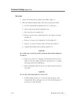
Hammer Spring
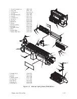
(Figure 6–8)
Removal
1. Remove the ribbon deck assembly as described on page 6–8.
2. Place the hammer bank assembly in the service position, as follows:
a.
Set the forms thickness adjustment lever (1) to fully open.
b. Remove the velcro pad (2) holding the wires.
c.
Disconnect the coil connectors (3).
d. Remove four screws (4), eight washers (23, 24), and two coil lead
brackets (5).
e.
Remove two screws (6), lockwashers (7), and washers (8).
f.
Remove two screws (9) and washers (10) from the shroud (11).
g. Separate the shroud from the shuttle assembly (12).
CAUTION
Be careful to prevent shims and the antirotation block from falling into
the printer.
h. Remove two screws (13). Separate the antirotation block (14) and
shims (15) from the shuttle assembly by applying force to compress
the spring on the side and lifting up.
i.
Rotate the hammer bank (16) as far as it will go toward the front of
the printer.
CAUTION
Do not loosen the bearing block set screws (25).
j.
Pull the hammer bank cover (17) away from the magnets on the
hammer bank. Then, disengage the cover from the holding pins (18)
and remove it from the printer.
Summary of Contents for P9012
Page 1: ...P N 132305 001 Rev E P9012 Multifunction Line Printer...
Page 49: ...2 31 Principles of Operation Power Supply PCBAs 1 3 SHORT OPEN Figure 2 21 Power Supply PCBA...
Page 58: ...2 40 Principles of Operation...
Page 84: ...4 18 Troubleshooting...
Page 118: ...5 34 Alignments and Adjustments...
Page 203: ...6 85 Replacement Procedures This page intentionally left blank...
Page 214: ...6 96 Replacement Procedures...
Page 236: ...A 22 Power Paper Stacker Maintenance...
Page 246: ...D 2 Torque Table...
Page 254: ...Index 6...
Page 255: ......
Page 256: ...132305 001 Rev E...

