6–37
Replacement Procedures
5
11
6
3
7
8
2
1
4
10
9
1. Screw
101514–041
2. MPU Arm
101240–001
3. Flywheel Assembly
131865–903
4. Support Plate
101132–001
5. Screw (2)
101514–042
6. Lockwasher (2)
102158–002
7. Shuttle Belt
101768–003
8. Base Support
132288–001
9. Roll Pin
101556–005
10. Cam
Part of item 3
11. Cam Wick
132072–001
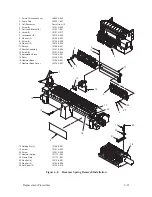
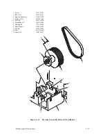
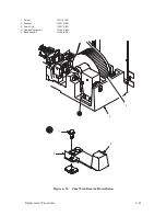
Figure 6–11. Flywheel Assembly Removal/Installation
Summary of Contents for P9012
Page 1: ...P N 132305 001 Rev E P9012 Multifunction Line Printer...
Page 49: ...2 31 Principles of Operation Power Supply PCBAs 1 3 SHORT OPEN Figure 2 21 Power Supply PCBA...
Page 58: ...2 40 Principles of Operation...
Page 84: ...4 18 Troubleshooting...
Page 118: ...5 34 Alignments and Adjustments...
Page 203: ...6 85 Replacement Procedures This page intentionally left blank...
Page 214: ...6 96 Replacement Procedures...
Page 236: ...A 22 Power Paper Stacker Maintenance...
Page 246: ...D 2 Torque Table...
Page 254: ...Index 6...
Page 255: ......
Page 256: ...132305 001 Rev E...


