6–24
Replacement Procedures
CAUTION
Do not lubricate the bearing block assemblies or hammer bank shaft.
3. Clean the hammer bank cover with a soft cloth moistened with isopropyl
alcohol.
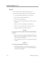
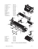
4. Remove the hammer spring screw (19). Loosen the screw (20).
5. Slide the hammer spring (21) forward past the clamp plate (22) and
remove.
Installation
CAUTION
Transport new hammer springs flat and unstressed. Handle carefully to
prevent damage to the hammer tips.
1. Slide the hammer spring under the clamp plate. Make sure the surfaces
that contact the spring are clean and free of burrs.
2. Install screw (19) finger tight. Align the hammer tips as described on
page 5–16 of Chapter 5, Alignments and Adjustments.
3. Return the hammer bank to the operating position by performing the
following:
a.
Install the hammer bank cover. Check for engagement with the
holding pins.
b. Rotate the hammer bank as far as it will go toward the rear of the
printer.
CAUTION
Do not lubricate the bearing block assemblies or hammer bank shaft.
c.
Apply a 1/4” drop of grease to both sides of the plate of the hammer
bank where the plate contacts the bearing surfaces of the antirotation
block.
d. Place the antirotation block and shim on the shuttle assembly by
forcing the slide toward the rear of printer. Install two screws (13).
Summary of Contents for P9012
Page 1: ...P N 132305 001 Rev E P9012 Multifunction Line Printer...
Page 49: ...2 31 Principles of Operation Power Supply PCBAs 1 3 SHORT OPEN Figure 2 21 Power Supply PCBA...
Page 58: ...2 40 Principles of Operation...
Page 84: ...4 18 Troubleshooting...
Page 118: ...5 34 Alignments and Adjustments...
Page 203: ...6 85 Replacement Procedures This page intentionally left blank...
Page 214: ...6 96 Replacement Procedures...
Page 236: ...A 22 Power Paper Stacker Maintenance...
Page 246: ...D 2 Torque Table...
Page 254: ...Index 6...
Page 255: ......
Page 256: ...132305 001 Rev E...


