


Device Configuration 5 - 263
•
Outside
- Packets passing through the NAT on the way back to the LAN are searched against the records kept by the NAT
engine. There the destination IP address is changed back to the specific internal private class IP address in order to reach
the LAN over the network.
•
None
- No NAT activity takes place. This is the default setting.
29. Select
OK
to save the changes to the basic configuration. Select
Reset
to revert to the last saved configuration.
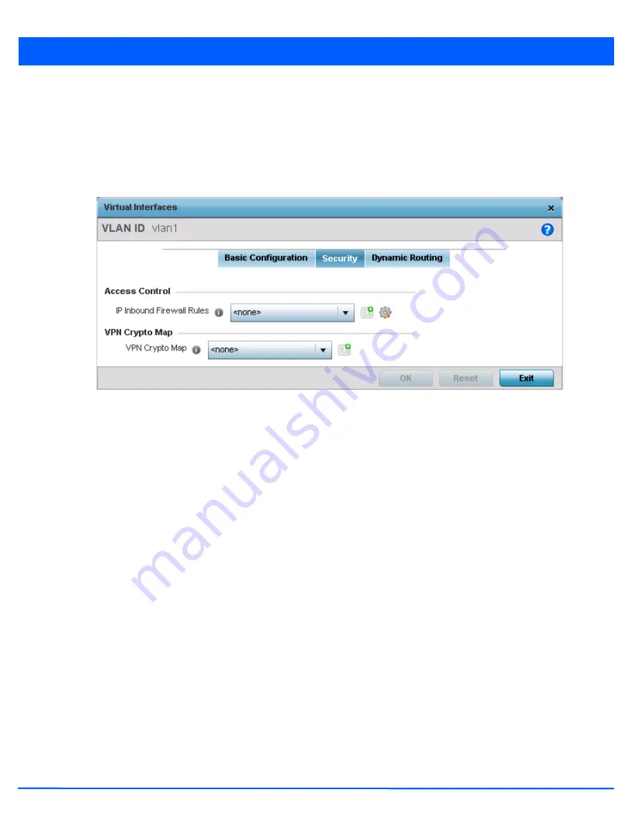
30. Select the
Security
tab.
Figure 5-163
OSPF Virtual Interface - Security screen
31. Use the
Inbound IP Firewall Rules
drop-down menu to select the IP access and deny rules to apply to the OSPF dynamic
route.
32. Either select an existing IP firewall policy or use the default set of IP firewall rules. The firewall inspects OSPF route traffic
flows and detects potential attacks on the dynamic route not visible to traditional wired firewall appliances. Select the
Create
icon to define a new set of IP firewall rules that can be applied to the OSPF route configuration. Selecting
Edit
allows for the modification of an existing IP firewall rules configuration. For more information, see
Wireless Firewall on
page 8-2
.
33. Select the
VPN Crypto Map
to use with this VLAN configuration. Use the drop-down menu to apply an existing crypto map
configuration to this VLAN interface. Use the
Create
icon to create a new VPN Crypto Map or use the
Edit
icon to edit an
existing VPN Crypto Map configuration before applying it to this VLAN.
Crypto Map entries are sets of configuration parameters for encrypting packets passing through the VPN Tunnel. If a Crypto
Map configuration does not exist suiting the needs of this virtual interface, select the
Create
icon to define a new Crypto
Map configuration or the
Edit
icon to modify an existing configuration.
34. Select
OK
to save the changes to the OSPF route security configuration. Select
Reset
to revert to the last saved
configuration.
35. Select the
Dynamic Routing
tab.
Summary of Contents for AP-7131 Series
Page 1: ...Motorola Solutions WiNG 5 5 ACCESS POINT SYSTEM REFERENCE GUIDE ...
Page 2: ......
Page 14: ...x WiNG 5 5 Access Point System Reference Guide ...
Page 22: ...8 WiNG 5 5 Access Point System Reference Guide ...
Page 26: ...1 4 WiNG 5 5 Access Point System Reference Guide ...
Page 74: ...3 36 WiNG 5 5 Access Point System Reference Guide ...
Page 428: ...6 2 WiNG 5 5 Access Point System Reference Guide Figure 6 1 Configuration Wireless menu ...
Page 528: ...6 102 WiNG 5 5 Access Point System Reference Guide ...
Page 610: ...8 40 WiNG 5 5 Access Point System Reference Guide ...
Page 615: ...Services Configuration 9 5 Figure 9 2 Captive Portal Policy screen Basic Configuration tab ...
Page 656: ...9 46 WiNG 5 5 Access Point System Reference Guide ...
Page 670: ...10 14 WiNG 5 5 Access Point System Reference Guide ...
Page 682: ...11 12 WiNG 5 5 Access Point System Reference Guide ...
Page 721: ...Operations 12 39 Figure 12 40 Certificate Management Import New Trustpoint screen ...
Page 738: ...12 56 WiNG 5 5 Access Point System Reference Guide ...
Page 890: ...A 2 WiNG 5 5 Access Point System Reference Guide ...
Page 952: ...B 62 WiNG 5 5 Access Point System Reference Guide ...
Page 953: ......


