Page 63
DANGER !
Do not activate the positioning mode unless you have adjusted the motor parameters and
the current and speed controller.
Incorrect basic settings may destroy the servo positioning controller, the motor and the
mechanical drive!
5.2 Configuring and optimizing the position controller
In positioning mode, a superordinated position controller is active in addition to the speed control. This
position controller processes the deviation of the actual position from the set position and converts it
into the corresponding setpoints for the speed controller. The position controller generates a correction
speed on the basis of the difference between the set position and the actual position and transfers this
speed value as a setpoint to the speed controller.
The position controller is used in conjunction with the positioning control system. It is a P-controller with
parameterizable input and output limitations.
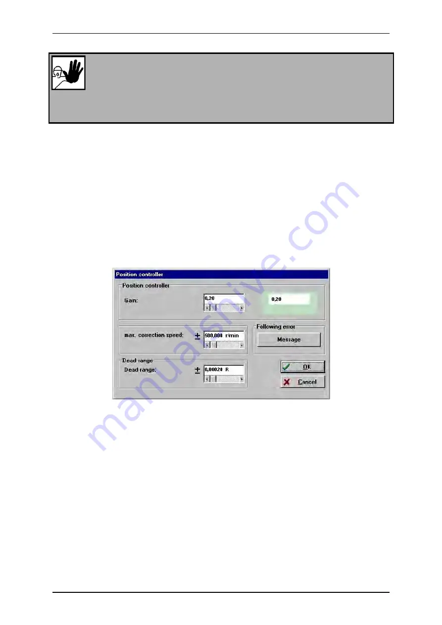
You can open the window for parameterizing the position controller under
Parameters/Controller
parameters/Position controller
.
Enter the following values:
Gain:
Max. correction speed:
In this field you can define the speed to be added to the running speed in the event of a deviation
between the position setpoint and the actual position. At the beginning, it should be set to about +/-
500 rpm.
Dead range:
Here you can state an admissible distance between the setpoint value and the actual value within
which the position controller stays inactive. The dead range can suppress oscillations which may
occur when encoders with a low resolution are used, e.g. in block-commutated drives with position
recirculation exclusively through the Hall sensor integrated in the motor. The dead range should be
set to zero to reach the highest possible position accuracy.
Following error:
Parameterization of a following error and a response delay. When the deviation between the
setpoint and the actual value is greater than the configured limit, a message or an error will be
issued. The reaction has to be set accordingly in the fault management system.
User Manual DUET_FL „DUET_FL 48/10“
Version 1.1 Motor Power Company
Summary of Contents for DUET_FL 48/10
Page 3: ...ber dieses Handbuch Page 3...
Page 4: ...Page 4 User Manual DUET_FL DUET_FL 48 10 Version 1 1 Motor Power Company...
Page 12: ...Page 12 List of Figures User Manual DUET_FL DUET_FL 48 10 Version 1 1 Motor Power Company...
Page 15: ...Page 15 List of Tables User Manual DUET_FL DUET_FL 48 10 Version 1 1 Motor Power Company...
Page 76: ...Page 76 User Manual DUET_FL DUET_FL 48 10 Version 1 1 Motor Power Company...
Page 196: ...Page 196 User Manual DUET_FL DUET_FL 48 10 Version 1 1 Motor Power Company...


