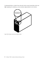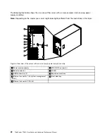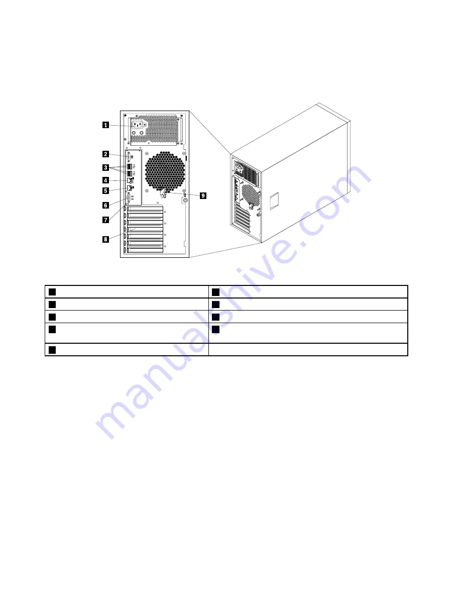
The following illustration shows the rear view of the server with a screw-secured, non-hot-swap power
supply assembly.
Note:
Depending on the model, your server might look slightly different from the illustrations in this topic.
Figure 6. Rear view of the server with a non-hot-swap power supply assembly
1
Power cord connector
6
VGA DB-15 connector
2
Serial connector
7
ID LED
3
USB connectors (4)
8
Expansion card area
4
Ethernet connector 1 for system management
(RJ-45)
9
Front door key
5
Ethernet connector 2 (RJ-45)
22
ThinkServer TD340 User Guide and Hardware Maintenance Manual
Summary of Contents for 70B4
Page 16: ...4 ThinkServer TD340 User Guide and Hardware Maintenance Manual ...
Page 18: ...6 ThinkServer TD340 User Guide and Hardware Maintenance Manual ...
Page 94: ...82 ThinkServer TD340 User Guide and Hardware Maintenance Manual ...
Page 220: ...208 ThinkServer TD340 User Guide and Hardware Maintenance Manual ...
Page 230: ...218 ThinkServer TD340 User Guide and Hardware Maintenance Manual ...
Page 244: ...232 ThinkServer TD340 User Guide and Hardware Maintenance Manual ...
Page 245: ......
Page 246: ......

