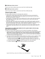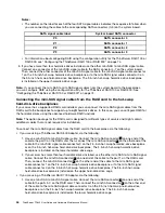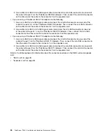
The following table provides information about the recommended power connector and system board SATA
connector for the non-hot-swap hard disk drive installed in each drive bay. See “Server components” on
page 28 and “System board components” on page 48 for the location information about the hard disk drive
bays and SATA connectors on the system board.
Non-hot-swap hard disk drive
Power connector
System board SATA connector
Installed in bay 0
P9 power connector
SATA connector 0
Installed in bay 1
P10 power connector
SATA connector 1
Installed in bay 2
P7 power connector
SATA connector 2
Installed in bay 3
P8 power connector
SATA connector 3
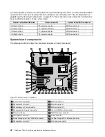
System board components
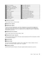
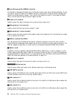
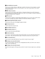
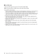
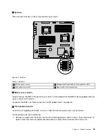
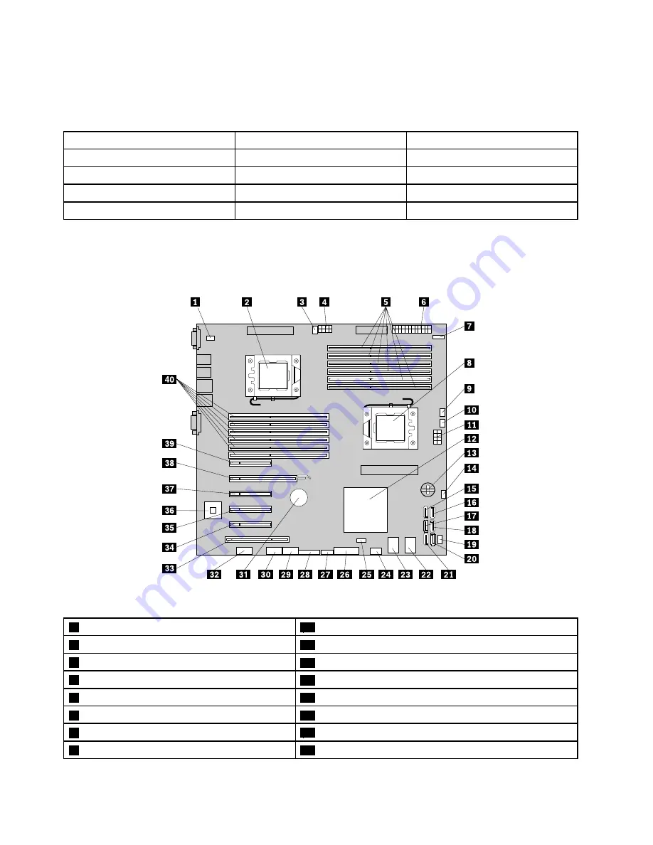
The following illustration shows the component locations on the system board.
Figure 29. System board components
1
System fan 3 connector
21
SATA connector 4
2
Microprocessor socket 2
22
SAS connector 4-7
3
Microprocessor 2 fan connector
23
SAS connector 0-3
4
Microprocessor 2 power connector
24
Internal USB Type A connector
5
Memory slots (6)
25
TMM Premium connector
6
Main power connector
26
TPM connector
7
Power Management Bus (PMBus) connector
27
Intelligent Diagnostics Module connector
8
Microprocessor socket 1
28
Front panel connector
48
ThinkServer TD340 User Guide and Hardware Maintenance Manual
Summary of Contents for 70B4
Page 16: ...4 ThinkServer TD340 User Guide and Hardware Maintenance Manual ...
Page 18: ...6 ThinkServer TD340 User Guide and Hardware Maintenance Manual ...
Page 94: ...82 ThinkServer TD340 User Guide and Hardware Maintenance Manual ...
Page 220: ...208 ThinkServer TD340 User Guide and Hardware Maintenance Manual ...
Page 230: ...218 ThinkServer TD340 User Guide and Hardware Maintenance Manual ...
Page 244: ...232 ThinkServer TD340 User Guide and Hardware Maintenance Manual ...
Page 245: ......
Page 246: ......

