Notes:
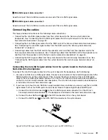
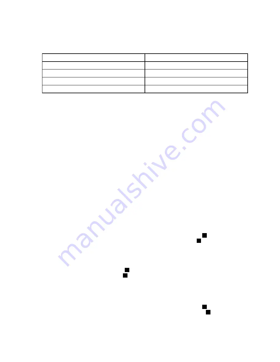
• The number on the label for each of the four SATA signal cables indicates the sequence to follow when
you are connecting the cables to the corresponding SATA connectors (0-3) on the system board.
SATA signal cable label
System board SATA connector
P0
SATA connector 0
P1
SATA connector 1
P2
SATA connector 2
P3
SATA connector 3
• For information about configuring RAID using the configuration utility for the ThinkServer RAID 100 or
RAID 300, see “Configuring the ThinkServer RAID 100 or RAID 300” on page 74.
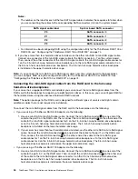
3. If you have more than four hard disk drives installed, use the other mini-SAS to mini-SAS signal cable.
Connect one connector of the mini-SAS signal cable to the SAS connector 4-7 on the system board.
Then, connect the other connector of the mini-SAS signal cable to the mini-SAS signal cable connector
1 on the 2.5-inch hot-swap hard-disk-drive backplane or to the mini-SAS signal cable connector 0 on
the 3.5-inch hot-swap hard-disk-drive backplane. The 3.5-inch hot-swap hard-disk-drive backplane
is installed on the upper hard-disk-drive cage.
Note:
If you connect the mini-SAS to mini-SAS signal cables from the system board to the backplanes,
you can configure RAID using the configuration utility for the ThinkServer RAID 100 or RAID 300. See
“Configuring the ThinkServer RAID 100 or RAID 300” on page 74.
Connecting the mini-SAS signal cables from the RAID card to the hot-swap
hard-disk-drive backplanes
If your server has a supported RAID card installed, you can connect the mini-SAS signal cables from the
RAID card to the backplanes to support up to eight hard disk drives. In this case, you can configure RAID for
the hard disk drives using the advanced hardware RAID functions.
Note:
The option package for the RAID card is designed for different types of servers and might contain
additional cables that are not required for installation.
To connect the mini-SAS signal cables from the RAID card to the backplanes, do the following:
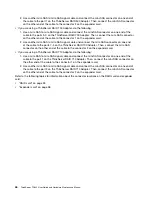
• If you are using a ThinkServer RAID 500 Adapter, do the following:
1. Use one mini-SAS to mini-SAS signal cable. Connect the mini-SAS connector
1
on one end of the
cable to the port 0 on the RAID card. Then, connect the mini-SAS connector
2
on the other end of the
cable to the mini-SAS signal cable connector 0 on the 2.5-inch hot-swap hard-disk-drive backplane
or on the 3.5-inch hot-swap hard-disk-drive backplane. The 3.5-inch hot-swap hard-disk-drive
backplane is installed on the lower hard-disk-drive cage.
2. If your server has more than four hard disk drives installed, use the other mini-SAS to mini-SAS signal
cable. Connect the mini-SAS connector
3
on one end of the cable to the port 1 on the RAID card.
Then, connect the mini-SAS connector
4
on the other end of the cable to the mini-SAS signal
cable connector 1 on the 2.5-inch hot-swap hard-disk-drive backplane or to the mini-SAS signal
cable connector 0 on the 3.5-inch hot-swap hard-disk-drive backplane. The 3.5-inch hot-swap
hard-disk-drive backplane is installed on the upper hard-disk-drive cage.
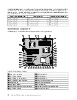
• If you are using a ThinkServer RAID 700 Adapter, do the following:
1. Use one mini-SAS to mini-SAS signal cable. Connect the mini-SAS connector
3
on one end of the
cable to the ports 3-0 on the RAID card. Then, connect the mini-SAS connector
4
on the other end
of the cable to the mini-SAS signal cable connector 0 on the 2.5-inch hot-swap hard-disk-drive
backplane or on the 3.5-inch hot-swap hard-disk-drive backplane. The 3.5-inch hot-swap
hard-disk-drive backplane is installed on the lower hard-disk-drive cage.
44
ThinkServer TD340 User Guide and Hardware Maintenance Manual
Summary of Contents for 70B4
Page 16: ...4 ThinkServer TD340 User Guide and Hardware Maintenance Manual ...
Page 18: ...6 ThinkServer TD340 User Guide and Hardware Maintenance Manual ...
Page 94: ...82 ThinkServer TD340 User Guide and Hardware Maintenance Manual ...
Page 220: ...208 ThinkServer TD340 User Guide and Hardware Maintenance Manual ...
Page 230: ...218 ThinkServer TD340 User Guide and Hardware Maintenance Manual ...
Page 244: ...232 ThinkServer TD340 User Guide and Hardware Maintenance Manual ...
Page 245: ......
Page 246: ......

