No additional pulsed laser 470 or 640 for MP systems
Systems equipped with an MP laser cannot be complemented with a
pulsed 440, 470, or 640-nm laser.
142
FLIM Data Acquisition
16.2.2.4
Using White Light Lasers
1. To activate the laser, follow the instructions in
. In general we recommend
using the filters available in the fluorifier disc.
2. If the white light laser is used as an excitation source for FLIM measurements, always
use only one wavelength per FLIM measurement.
16.2.3
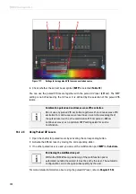
Adjusting the Fluorifier Disc
With the
Show Fluorifier Settings
button (
), you can call up the
Fluorifier Disc
Settings
dialog to select a barrier filter or set a polarization angle.
16.2.3.1
Setting for SP FLIM
SMD systems equipped with SP FLIM detectors have a fluorifier disc with barrier filters for
the excitation light. These filters prevent reflected excitation light from hitting the SP
module.
Alternative selection of UV and MP FLIM excitation
Some systems feature both a pulsed diode laser (405 nm) and an MP
laser. Only one of these two lasers can be used for FLIM at a time. Make
sure that the correct synchronization cable is connected to the TCSPC
unit PicoHarp 300 at channel 0. When changing between MP and 405 nm
excitation for FLIM, you must also change the synchronization cable
connected to the PicoHarp.
Alternative selection of excitation from a white light laser, pulsed
diode, or MP FLIM
Some systems feature not only a white light laser, but also a pulsed laser
and/or an MP laser. Only one of these three laser options can be used for
FLIM at a time. Make sure that the correct synchronization cable is
connected to the TCSPC unit PicoHarp 300 at channel 0. When changing
between MP, white light laser, or diode laser for FLIM, you must also
change the synchronization cable connected to the PicoHarp.
Summary of Contents for TCS SP8 SMD
Page 1: ...10 Living up to Life User Manual Leica TCS SP8 SMD for FCS FLIM and FLCS ...
Page 4: ...4 Copyright ...
Page 14: ...14 Contents ...
Page 18: ...18 Intended Use ...
Page 20: ...20 Liability and Warranty ...
Page 28: ...28 General Safety Notes ...
Page 32: ...32 Additional Notes on Handling the System ...
Page 44: ...44 System Overview and Properties ...
Page 60: ...60 SMD Components Figure 31 DSN 102 Dual SPAD Power Supply ...
Page 80: ...80 Safety Features ...
Page 102: ...102 Switching On the System ...
Page 116: ...116 LAS AF ...
Page 214: ...214 Changing the Specimen ...
Page 216: ...216 Changing the Objective ...
Page 238: ...238 Switching Off the System ...
Page 242: ...242 Repairs and Service Work ...
Page 244: ...244 Maintenance ...
Page 246: ...246 Disassembly and Transport ...
Page 248: ...248 Disposal ...
Page 254: ...254 Contact ...
Page 256: ...256 Recommended Literature ...
Page 266: ...266 Appendix Figure 225 Declaration of conformity ...
Page 268: ...268 Appendix ...
Page 269: ......


