background image

100

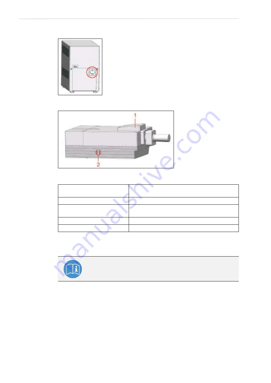
Switching On the System

Figure 80: 

HyD RLD supply unit

Figure 81: 

HyD Reflected Light Detectors (HyD RLDs)

13.4

Starting the SMD Hardware and Software

In the following we assume a running confocal system with the specimen already in place 
and in focus. The target region for FLIM or FCS measurements has already been determined 
(

Chapter 15

Chapter 18.1.5

Chapter 18.1.6

 and 

Chapter 18.2

). The SMD upgrade can be 

started completely independently from the Leica TCS SP8. 

Start the SMD upgrade hardware and software in the following sequence: 

1. Check whether the SMD workstation is started. 

2. Make sure that all devices in the trolley are started. If the instruments are not supplied 

with electricity despite multiple socket outlets being switched on, check whether the 

Status LED color
(see Figure 81, item 2)

Meaning

Green

Operational readiness

Red

The maximum permitted signal level was exceeded. The 
detector was shutoff.

Yellow

Flashes if photons are being detected.

Blue

Cooling is active.

Observe the user manuals provided

Always observe all of the user manuals provided for the individual 
components and peripheral devices.

Summary of Contents for TCS SP8 SMD

Page 1: ...10 Living up to Life User Manual Leica TCS SP8 SMD for FCS FLIM and FLCS ...

Page 2: ...a microsystems com http www confocal microscopy com Responsible for contents Leica Microsystems CMS GmbH Copyright Leica Microsystems CMS GmbH All rights reserved This manual was created in cooperation with PicoQuant GmbH PicoQuant GmbH Rudower Chaussee 29 12489 Berlin Germany http www picoquant com ...

Page 3: ...All rights reserved Reproduction adaptation or translation of these programs is prohibited without prior written permission from Leica Microsystems CMS GmbH This User Manual specifies names of products or services that are trademarks or registered trademarks of the respective trademark owners Rather than including a trademark TM or symbol at every occurrence of a trademarked name we state that we ...

Page 4: ...4 Copyright ...

Page 5: ... 26 6 Additional Notes on Handling the System 29 6 1 Location 29 6 2 Using the Software 29 6 3 Protecting the System 30 6 3 1 Objectives 31 7 System Overview and Properties 33 7 1 TCS SP8 SMD System Variants 33 7 1 1 TCS SP8 SMD System Components 33 7 1 2 TCS SP8 SMD with Upright Microscope 34 7 1 3 TCS SP8 SMD with Inverted Microscope 34 7 2 TCS SP8 SMD System Variants with White Light Laser 35 7...

Page 6: ...y of the multiple socket outlet on the flexible supply unit 49 8 6 Waste Heat and Cooling 49 8 6 1 System with Flexible Supply Unit 50 8 6 2 System with Compact Supply Unit Only with FLIM 50 8 6 3 External Lasers 50 9 SMD Components 51 9 1 Hardware Components and Software Licenses 51 9 1 1 FCS FCCS Application Area 51 9 1 1 1 Special SMD Hardware 51 9 1 1 2 Software License 51 9 1 2 FLIM Applicati...

Page 7: ...tosecond laser 64 10 5 Overview of Usable Lasers for FLCS 66 10 5 1 VIS UV Lasers for TCS SP8 SMD 66 11 Safety Features 67 11 1 Main Circuit Breaker for Disconnecting the Power Supply 67 11 1 1 Compact Supply Unit 67 11 1 2 Flexible Supply Unit 67 11 1 3 Other Components 68 11 2 Key Switch 68 11 2 1 Master Key Switch on the Compact Supply Unit 68 11 2 2 Master Key Switch on the Flexible Supply Uni...

Page 8: ...Upright Microscope 84 12 5 Mirror Housing 85 12 6 Cover for Replacement Flange 86 12 7 Transmitted Light Detector TLD Reflected Light Detector RLD 87 12 8 Scan Head 87 12 9 White Light Laser 89 12 10 External UV Laser 89 12 11 MP Beam Coupling Unit 90 12 12 Other External Lasers 90 13 Switching On the System 91 13 1 Confocal System with Flexible Supply Unit 91 13 2 Confocal System with Compact Sup...

Page 9: ... Using Continuous Wave Lasers 130 16 1 2 2 Using MP Lasers 131 16 1 2 3 Using Pulsed VIS Lasers 131 16 1 2 4 Using Pulsed UV Lasers 132 16 1 2 5 Using White Light Lasers 133 16 1 3 Adjusting the Pinhole for Image Acquisition 133 16 2 Setup FLIM Step Optimizing the FLIM Measurement Conditions 134 16 2 1 Selecting FLIM Detectors 134 16 2 1 1 FLIM Data Acquisition with Internal SP FLIM Detectors 135 ...

Page 10: ...fining a Time Series of xy or xz FLIM Stacks 158 16 3 9 Defining an xy or xz FLIM Stack 160 16 3 10 Control of FLIM Measurements 162 17 Summarized Manual for FLIM Experiments 163 17 1 Prerequisites 163 17 2 Selecting Position for the FLIM Measurement 163 17 3 Changing from Continuous to Pulsed Excitation 163 17 4 Changing from Internal Detection on the SP8 to External TCSPC Detectors 164 17 5 Usin...

Page 11: ...s PDM Type 188 18 2 Setup Imaging Step Image Acquisition 190 18 2 1 Selecting Detectors for the Image Acquisition 190 18 2 1 1 Photomultiplier PMT Internal Hybrid Detector HyD 190 18 2 1 2 PE MPD APDs 190 18 2 2 Selecting Laser Lines as an Excitation Source for the Image Acquisition 191 18 2 2 1 Using Continuous Wave Lasers 191 18 2 2 2 Using MP Lasers 192 18 2 2 3 Using Pulsed VIS Lasers 192 18 2...

Page 12: ...ng the Specimen 213 20 1 Changing the Specimen on an Upright Microscope 213 20 2 Changing the Specimen on an Inverted Microscope 213 21 Changing the Objective 215 22 Piezo Focus on Upright Microscope 217 23 Changing the Filter Cube 219 24 Changing Detector Cable Connections on the Scan Head and Router When Using HyD RLD 221 24 1 Hardware Trees 222 24 1 1 MP on FCS FLIM 2 APD 223 24 1 2 MP off FCS ...

Page 13: ...eds to be Installed Again 249 31 2 The Instrument Is Losing Sensitivity 249 31 2 1 Causes for Decreased Performance 250 31 3 No FLIM Image is Displayed During Measurement 250 31 4 How to Handle PQ Error Codes in LAS AF 252 32 Contact 253 33 Recommended literature 255 34 Abbreviations 257 35 Appendix 259 35 1 Patents 259 35 2 Safety Data Sheets from Third Party Manufacturers 259 35 3 Compliance 265...

Page 14: ...14 Contents ...

Page 15: ... list of abbreviations used in this manual This operating manual was created by PicoQuant GmbH and Leica Microsystems CMS GmbH and is concentrated on specialized knowledge about SMD Single Molecule Detection The basic procedures for acquiring FLIM images and point measurements for FCS using the TCS SMD system are described here This User Manual does not contain any information about basic optical ...

Page 16: ...on about single photon counting Light sources The green folder contains detailed information about the features of your pulsed diode laser Router PHR800 The router is required in systems with multiple detectors Laser driver PDL The manual for the laser driver varies depending on the laser driver used and includes information for configuring different intensities Software SymPhoTime Contains all in...

Page 17: ...care wards The owner operator and user of this product are responsible for proper and safe operation and safe maintenance of the system and for following all applicable safety regulations The owner operator and user are fully liable for all consequences resulting from the use of the system for any purposes other than those listed in the User Manual or the online help The manufacturer assumes no li...

Page 18: ...18 Intended Use ...

Page 19: ...crosystems CMS GmbH shall not be liable for any injury or property damage caused by untrained or unauthorized persons 3 1 Important Information for Operators and Users The owner operator is required to designate a Laser Safety Officer or a Laser Protection Advisor according to the applicable legal requirements in each country The owner operator and user of this product are responsible for proper a...

Page 20: ...20 Liability and Warranty ...

Page 21: ... severe or fatal injuries WARNING Permanent eye and skin damage from laser radiation This note warns you of eye and skin damage that can occur when using lasers if safety precautions are not taken WARNING Risk of injuries due to harmful or irritating substances This note warns you of substances that pose a health hazard WARNING Risk of injuries due to biological substances This note warns you of b...

Page 22: ...is note warns you of the potential for losing data Observe user manual This mandatory sign indicates that an additional user manual must be followed Wear laser safety glasses This mandatory sign indicates that laser safety glasses must be worn to prevent eye injuries Additional note This note serves to emphasize important instructions for handling the product or contains special instructions about...

Page 23: ...laser safety glasses This applies to all persons present in the room where the system is set up and operated Each user must have read the instructions included and follow the instructions it contains Specimens must always be securely fixed in place Do not introduce any flammable objects such as paper into the specimen area when you are working with a laser Do not place any flammable or combustible...

Page 24: ...laser protection devices All safety devices must be ready to operate Do not carry out any procedures that modify disable or damage the functionality of safety features Unauthorized procedures could result in serious injuries or property damage Safety labels on the system may not be removed Missing or damaged safety labels must be attached immediately and at the described location Observe Chapter S...

Page 25: ...imit value that eliminates the chance for eye injuries Do not use an S70 microscope condenser The large working distance and the low numerical aperture of the S70 microscope condenser could result in a hazard from laser radiation Only use S1 and S28 Leica microscope condensers Do not look into the eyepieces during the scanning operation Never change samples during a scanning operation Never change...

Page 26: ...ded or provided by your local Leica service technicians for connecting individual peripheral devices to the power supply Fuses inside the system may be replaced only by authorized Leica service employees If you have any further questions please directly contact the Leica branch office in your country Check that the actual line voltage corresponds to the value configured on the PDL 800 B or D laser...

Page 27: ...27 General Safety Notes If any of these occur immediately notify the Leica branch office in your country or your local contact person ...

Page 28: ...28 General Safety Notes ...

Page 29: ...ons applicable for this system You may use the system indoors only The room must be free of dust oil and chemical vapors After installing the system you may carry out interior finish work on the room only if the system is stored in a dust free location while this work is underway Avoid direct sunlight and vibrations since these can distort measurements and micrographic scans We recommend using a r...

Page 30: ...temperature fluctuations Such fluctuations can lead to the accumulation of condensation which can damage the electrical and optical components Allow the entire system to cool down to room temperature before covering the system with a dust cover This prevents condensation from forming below it which can enter the system and damage it When used as intended the HyD reflected light detectors are suffi...

Page 31: ...e objective Unsuitable immersion fluid can contaminate or destroy the objective When changing over from an oil or water objective to a dry objective you have to remove the immersion medium from the specimen slide in order not to damage the dry objective Never open the objectives for cleaning If there is a piezo focus installed on your system be absolutely certain to observe the corresponding notes...

Page 32: ...32 Additional Notes on Handling the System ...

Page 33: ...exible supply unit as an example 1 Trolley with external lasers detectors and their controllers 8 TCS SP8 workstation 9 Main switch board on the supply unit 2 SMD workstation 10 Control panel 3 Fluorescence lamp EL6000 11 KVM switch 4 Multifunction port MFP on the scan head 12 SmartMove only with motorized table 5 Scan head 13 Upright microscope 6 X1 port on the scan head 14 Microscope electronics...

Page 34: ...CS SP8 SMD with Upright Microscope Figure 3 Dimensions of TCS SP8 SMD with upright microscope and flexible supply unit 7 1 3 TCS SP8 SMD with Inverted Microscope Figure 4 TCS SP8 SMD dimensions with inverted microscope and flexible supply unit ...

Page 35: ...e and PicoQuant laser as an example 1 Trolley with external lasers detectors and their controllers 8 TCS SP8 workstation 9 Main switch board on the supply unit 2 SMD workstation 10 Control panel 3 Fluorescence lamp EL6000 11 KVM switch 4 Multifunction port MFP on the scan head 12 SmartMove only with motorized table 5 Scan head 13 Upright microscope 6 X1 port on the scan head 14 Microscope electron...

Page 36: ...MD with White Light Laser and Upright Microscope Figure 6 Dimensions of TCS SP8 SMD with white light laser upright microscope and PicoQuant laser Figure 7 Dimensions of TCS SP8 SMD with white light laser and upright microscope without PicoQuant laser ...

Page 37: ...D with White Light Laser and Inverted Microscope Figure 8 Dimensions of TCS SP8 SMD with white light laser inverted microscope and PicoQuant laser Figure 9 Dimensions of TCS SP8 SMD with white light laser and inverted microscope without PicoQuant laser ...

Page 38: ...onal accessories please look at the Leica TCS SP8 MP Room Requirements Figure 10 System overview of TCS SP8 SMD with MP configuration upright and inverted microscope possible 1 Trolley with external lasers detectors and their controllers 5 Optical table 150 x 120 cm 4 11 x 3 11 6 Upright or inverted microscope 2 SMD workstation 7 Beam coupling unit 3 Microscope electronics box EL6000 fluorescence ...

Page 39: ...hite light lasers 5 Optical table 150 x 120 cm 4 11 x 3 11 6 Upright or inverted microscope 2 SMD workstation 7 Beam coupling unit 3 Microscope electronics box EL6000 8 Infrared IR laser 4 Stage with supply unit 9 Power supply and cooling of the IR laser 1 White light laser 6 Optical table 150 x 120 cm 4 11 x 3 11 2 Trolley with detectors their controllers and PicoQuant lasers 7 Upright or inverte...

Page 40: ...t 7 4 1 Main Switch Board on the Flexible Supply Unit Figure 13 Overview of the main switch board on the flexible supply unit 7 4 2 Control Panel Field on the Compact Supply Unit Only for FLIM Figure 14 Overview of the control panel field on the Compact supply unit ...

Page 41: ...ed microscope and PicoQuant laser 414 x 120 x 150 cm 13 7 x 3 11 x 4 11 TCS SMD for TCS SP8 X with inverted microscope without PicoQuant laser 364 x 120 x 150 cm 11 11 x 3 11 x 4 11 TCS SMD for TCS SP8 MP max 490 x 120 x 175 cm 16 1 x 3 11 x 5 9 TCS SMD for TCS SP8 X with MP configuration without PicoQuant laser max 490 x 120 x 175 cm 16 1 x 3 11 x 5 9 TCS SMD for TCS SP8 X with MP configuration a...

Page 42: ...an cause radio interference in a household environment In these cases the operator may have to take measures to eliminate the interference When using internal and external HyDs it is recommended that the system only be operated in a controlled electromagnetic environment This is because the use of cell phones or other radio transmitting devices such as DECT phones can cause picture interference if...

Page 43: ...43 System Overview and Properties 7 7 Serial Number The serial number for your system is located on the rear side of the scan head Figure 15 Rear side of the scan head label with serial number ...

Page 44: ...44 System Overview and Properties ...

Page 45: ...systems CMS GmbH for phone support For RemoteCare an Internet connection is also needed The system should be set up in a separate room in order to be able to provide a constant temperature and appropriate ambient lighting without having to address needs of other systems instruments and room users Temperature range for operation 18 to 25 C 64 to 77 F optimum optical behavior 22 C 1 C 72 F 1 8 F Pol...

Page 46: ...for the space Room dimensions length x depth TCS SP8 SMD with upright microscope compact and flexible supply unit possible 470 x 290 cm 15 5 x 9 6 TCS SP8 SMD with inverted microscope compact and flexible supply unit possible 484 x 290 cm 15 11 x 9 6 TCS SP8 SMD with white light laser upright microscope and PicoQuant laser 520 x 290 cm 17 1 x 9 6 TCS SP8 SMD with white light laser upright microsco...

Page 47: ...00 V 240 V fuse protection 12 16 A Two for the flexible supply unit s power supply and one for supplying peripheral devices To prevent damage to the instrument the two types of voltage 200 to 240 V and 100 to 120 V must not be combined Depending on the system configuration further electrical circuits may be required Power supply for USA Two terminals of the NEMA 5 20 type for the supply unit Termi...

Page 48: ...ystem configuration further electrical circuits may be required Power supply for USA Terminals of type NEMA 5 15 for the SMD rack a separate electric circuit with Power supply voltage 100 V to 240 V fuse protection 16 20 A dependent on local regulations for the infrared laser and its cooling system MP configuration a separate electric circuit with Power supply voltage 100 V to 240 V fuse protectio...

Page 49: ...the rear side of the multiple socket outlet on the flexible supply unit 8 6 Waste Heat and Cooling NOTICE Instruments may sustain damage Never install the system close to air conditioners or other ventilation systems Air from air conditioning systems or other ventilation equipment should not blow directly on the microscope Use a high performance air conditioning system We recommend a high performa...

Page 50: ...6 ft h For cooling the argon laser must be connected to the provided argon laser fan The following space is required In addition it is possible to connect the argon laser exhaust to an in house exhaust system The remaining waste heat must be extracted otherwise the room temperature will rise 8 6 2 System with Compact Supply Unit Only with FLIM Waste heat of the complete system with a compact suppl...

Page 51: ... Components and Software Licenses Depending on the field of application different hardware and software configurations are possible During single photon counting detection for time resolved measurements avalanche photodiodes APD or photomultipliers PMTs can be used 9 1 1 FCS FCCS Application Area 9 1 1 1 Special SMD Hardware Table 1 Special SMD hardware for FCS FCCS 9 1 1 2 Software License Table ...

Page 52: ...ia I LCU II via MFP in scan head 470 nm PDL800 B via MFP in scan head 470 nm 640 nm Sepia I LCU II via MFP in scan head 405 nm 470 nm 640 nm Sepia II LCU II via UV port and MFP in scan head WLL via AOBS MP with TDA trigger diode assembly via MFP Detectors for SMD External detection on the X1 port Either PDM APD from MPD MPD DSN102 or PMA photomultiplier And or internal detection SP FLIM photomulti...

Page 53: ...nd signal For FLIM additionally a high time resolution is necessary whereas for FCS a high quantum efficiency is crucial Therefore different detectors can be used depending on the field of application see Table 1 Table 4 and Table 6 When confocal external detectors are used light is split off to optical fibers at the external interface X1 X1 port with the aid of the X1 adapter then guided to the p...

Page 54: ...can head with APD detection at the external X1 port 9 3 Detection Units from PicoQuant The following detection units are available for SMD upgrades Figure 18 Single channel PMT detection unit Figure 19 Double channel PMT detection unit ...

Page 55: ... At the APD detector unit the APDs can be switched on independently of one another Figure 22 item 1 and 2 In addition to the switches for the APDs the front side of the control unit also includes indicators for the power supply Figure 22 item 3 The power switch itself is on the rear of the APD detector unit Figure 22 item 5 Figure 22 Leica APD detector unit The photon counting signal generated by ...

Page 56: ...cube 9 4 2 Changing the Fuse The fuse is in the device connector on the back of the APD detector unit When replacing the fuse there must be no voltage at the APD detector unit disconnect the mains plug 9 4 3 Safety Shutoff APDs are extremely sensitive detectors which can be damaged irreparably by light that is too intense such as room lighting For this reason APDs are protected by an automatic shu...

Page 57: ... polarization maintaining single mode PM SM laser Figure 25 This laser is coupled into the multifunction port MFP of the SP8 scan head In the UV range e g 405 nm a separate laser output is used that is coupled to the UV port of the SP8 scan head Figure 25 Laser Coupling Unit LCU WARNING Risk of permanent eye and skin damage from laser radiation The laser coupling unit must not be opened The adjust...

Page 58: ...0 1 transmission The additional scaffold allows a continuous attenuation 100 to 0 by clipping the laser beams The scaffold is controlled by a micrometer screw and enables precision control of the intensity Note that the attenuation unit is placed in a position where all laser beams come through This ensures that the attenuation of the ND filters neutral density filters is equal for all beams Howev...

Page 59: ...omponents Figure 27 PicoHarp 300 TCSPC unit Figure 28 Router PHR 800 A multi photomultiplier configuration is shown here Figure 29 Laser drivers for pulsed diode lasers PDL 828 Sepia II Figure 30 Laser drivers for pulsed diode lasers PDL 800 B ...

Page 60: ...60 SMD Components Figure 31 DSN 102 Dual SPAD Power Supply ...

Page 61: ... radiation UV 350 400 nm invisible laser radiation TCS SP8 SMD with MP configuration 4 IV VIS 400 700 nm visible laser radiation UV 350 400 nm invisible laser radiation IR 680 1600 nm invisible laser radiation 10 2 Overview of Usable Lasers for Image Acquisition 10 2 1 VIS UV Lasers for TCS SP8 The TCS SP8 features a combination of the lasers listed below Laser type Wavelength nm Maximum light out...

Page 62: ... HP ps 690 1040 3 5 1 9 pulsed 1 0 1 5 ps Chameleon Ultra II ps 680 1080 4 1 9 pulsed 1 0 1 5 ps OPSL 514 514 350 10 Continuous wave cw OPSL 552 552 350 10 Continuous wave cw DPSS 561 561 100 12 Continuous wave cw HeNe 594 4 1 Continuous wave cw HeNe 633 15 5 Continuous wave cw Diode 638 638 350 10 Continuous wave cw Laser type Wavelength nm Maximum light output at laser output mW Maximum light ou...

Page 63: ...50 3 5 1 9 pulsed 75 fs Chameleon Ultra II Compact OPO 680 1080 4 0 1 9 pulsed 140 fs 1000 1300 1 6 0 8 pulsed 100 fs Chameleon Vision II Compact OPO 680 1080 4 0 1 9 pulsed 140 fs 1000 1280 1 6 0 8 pulsed 100 fs 10 3 Overview of Usable Lasers for FCS 10 3 1 VIS UV Lasers for TCS SP8 SMD Laser type Wavelength nm Maximum light output at laser output mW Maximum light output in focal plane mW Pulse d...

Page 64: ...n The TCS SP8 SMD with MP configuration for FLIM can contain a combination of all the infrared lasers in Chapter 10 4 1 and the following infrared lasers 10 4 2 1 Picosecond laser Laser type Wavelength nm Maximum light output at laser output W Maximum light output in focal plane W Pulse duration MaiTai HP ps 690 1040 3 5 1 9 pulsed 1 0 1 5 ps Chameleon Ultra II ps 680 1080 4 1 9 pulsed 1 0 1 5 ps ...

Page 65: ...lsed 140 fs Chameleon Vision S 690 1050 3 5 1 9 pulsed 75 fs Chameleon Ultra II Compact OPO 680 1080 4 0 1 9 pulsed 140 fs 1000 1300 1 6 0 8 pulsed 100 fs Chameleon Vision II Compact OPO 680 1080 4 0 1 9 pulsed 140 fs 1000 1280 1 6 0 8 pulsed 100 fs ...

Page 66: ...lane mW Pulse duration 405 pulsed 405 3 40 MHz 0 1 40 MHz pulsed 80 ps 405 dual voltage 405 3 40 MHz 0 1 40 MHz Pulsed continuous wave cw 80 ps 440 440 3 40 MHz 0 1 40 MHz pulsed 80 ps 470 470 3 40 MHz 0 3 40 MHz pulsed 80 ps 640 640 4 5 40 MHz 0 5 40 MHz pulsed 80 ps White light laser 470 670 500 50 Pulsed The TCS SP8 SMD for FLCS features a combination of the lasers listed below ...

Page 67: ...er plug must be disconnected 11 1 2 Flexible Supply Unit The main circuit breaker is located on the right rear side of the flexible supply unit It is used to de energize the complete system using a single switch see Figure 32 The main circuit breaker functions as a switch and as an overcurrent fuse The main circuit breaker is not to be used as the regular on off switch for the system The supply un...

Page 68: ...e 33 Figure 33 Master key switch on the compact supply unit 11 2 2 Master Key Switch on the Flexible Supply Unit There is a master key switch on the flexible supply unit for protection against unauthorized use of the laser products This master key switch is integrated in the interlock circuit If the master key switch is in the off position all laser beam paths are interrupted Then no radiation fro...

Page 69: ...nal lasers can also be turned off individually The detachable key switch for protection against unauthorized use of the external white light laser is located on the front of the white light laser see Figure 35 Figure 35 Key switch for the white light laser 11 2 4 Key Switch for UV Lasers Figure 36 Key switch on the power supply of external UV laser 355 ...

Page 70: ...radiation may be present in the specimen area of the laser scanning microscope Make sure to follow the safety notes for operation of the system 11 3 1 Emission Warning Indicator on the Supply Unit The emission warning indicator on the supply unit is connected to the master key switch If this is illuminated there is the possibility of laser radiation in the specimen plane If the master key switch i...

Page 71: ...hite Light Laser The emission warning indicator of the achromatic light laser is located on the front of the achromatic light laser see Figure 40 and is red when lit Figure 40 Emission warning indicator on the white light laser 11 3 3 Emission Warning Indicator on UV Lasers Figure 41 Emission Warning Indicator on Power Supply of External UV Laser 355 ...

Page 72: ...nit The interlock connector plug connection for the remote controlled safety interlock is on the rear side of the supply unit Operating voltage is 12 V DC for the flexible supply unit see Figure 44 for the compact supply unit see Figure 43 The interlock connector on the supply unit has a shorting plug in its factory condition The shorting plug is removable in order to connect a remote controlled s...

Page 73: ...d 10 m If a large amount of electromagnetic interference EMC is expected in the environment use a shielded cable with a shielded plug Figure 43 Interlock connector on the compact supply unit Figure 44 Interlock connector on the rear side of the flexible supply unit ...

Page 74: ...ther External Lasers Observe the user manuals for external lasers Please refer to the information from the documents provided by the laser manufacturer for the external lasers Pay particular attention to the laser manufacturer s notes Interlock connector when using the white light laser If the white light laser is operated as a component of the TCS SP8 X system you have to use the interlock connec...

Page 75: ... operating voltage 12 V DC see Figure 46 For laser safety reasons the inverted microscope must be connected to this connection or if an upright microscope is used to the mirror housing This ensures that the microscope safety switch is integrated in the interlock circuit Figure 46 Position of the interlock connector on the scan head ...

Page 76: ...ut by motor Prevents stray light in the eyepiece if the user switches from eyepiece observation to confocal observation 3 Pushbutton in the port apertures of the mirror housing One of the two apertures on the mirror housing is free no external detector no halogen lamps no cover Prevents the escape of laser light if the user removes components from the mirror housing 11 6 Warning Messages Warning m...

Page 77: ...tem may not be operated Audible warning signal during automatic firmware update During the update of the firmware a continuous tone sounds After the updated component is automatically restarted the signal stops During the automatic update and the automatic restart of the component you may not switch off or restart the system since otherwise this can lead to damage to the system Warning signal in t...

Page 78: ...igure 48 item 3 The existing laser protection shield see Figure 48 item 3 must always be reinstalled Please consult the microscope s user manual provided Condenser Base with Filter Holder When using a condenser base with filter holder always make sure that unused filter holders are swung out of the beam path and that the laser protection tube covers the beam path When equipping multiple filter hol...

Page 79: ...e and therefore completely shielded until it leaves the microscope objective and reaches the specimen For systems with infrared laser wavelength range 700 nm the beam is passed through a safety beam guide and if necessary also passed through a fiber optic cable see Figure 49 This completely shields the laser beam until it leaves the microscope objective and reaches the specimen Figure 49 Safety be...

Page 80: ...80 Safety Features ...

Page 81: ... labels must be attached immediately and at the described location Operation without the safety labels shown is not permitted If you have any further questions contact your laser safety officer or the Leica branch office in your country immediately 12 1 Compact Supply Unit Only for FLIM View of the compact supply unit Figure 50 Safety labels on the compact supply unit Table 8 Safety Labels on the ...

Page 82: ...le supply unit Table 9 Safety Labels on the Flexible Supply Unit see Figure 51 Position Safety label in English Translation of the safety label 1 DANGER LASER RADIATION CLASS 3B WHEN OPEN AVOID EXPOSURE TO BEAM VORSICHT LASERSTRAHLUNG KLASSE 3B WENN ABDECKUNG GEÖFFNET NICHT DEM STRAHL AUSSETZEN ...

Page 83: ...ADIATION CLASS 3B WHEN OPEN AVOID EXPOSURE TO BEAM VORSICHT LASERSTRAHLUNG KLASSE 3B WENN ABDECKUNG GEÖFFNET NICHT DEM STRAHL AUSSETZEN UV DANGER VISIBLE AND INVISIBLE LASER RADIATION CLASS 3B WHEN OPEN AVOID EXPOSURE TO BEAM VORSICHT SICHTBARE UND UNSICHTBARE LASERSTRAHLUNG KLASSE 3B WENN ABDECKUNG GEÖFFNET NICHT DEM STRAHL AUSSETZEN MP DANGER VISIBLE AND INVISIBLE LASER RADIATION CLASS 4 WHEN OP...

Page 84: ...AM VORSICHT SICHTBARE UND UNSICHTBARE LASERSTRAHLUNG KLASSE 3B WENN ABDECKUNG GEÖFFNET NICHT DEM STRAHL AUSSETZEN MP DANGER VISIBLE AND INVISIBLE LASER RADIATION CLASS 4 WHEN OPEN AVOID EYE OR SKIN EXPOSURE TO DIRECT OR SCATTERED RADIATION VORSICHT SICHTBARE UND UNSICHTBARE LASERSTRAHLUNG KLASSE 4 WENN ABDECKUNG GEÖFFNET BESTRAHLUNG VON AUGE ODER HAUT DURCH DIREKTE ODER STREUSTRAHLUNG VERMEIDEN 2 ...

Page 85: ... WENN ABDECKUNG GEÖFFNET NICHT DEM STRAHL AUSSETZEN UV DANGER VISIBLE AND INVISIBLE LASER RADIATION CLASS 3B WHEN OPEN AVOID EXPOSURE TO BEAM VORSICHT SICHTBARE UND UNSICHTBARE LASERSTRAHLUNG KLASSE 3B WENN ABDECKUNG GEÖFFNET NICHT DEM STRAHL AUSSETZEN MP DANGER VISIBLE AND INVISIBLE LASER RADIATION CLASS 4 WHEN OPEN AVOID EYE OR SKIN EXPOSURE TO DIRECT OR SCATTERED RADIATION VORSICHT SICHTBARE UN...

Page 86: ...ANGER LASER RADIATION CLASS 3B WHEN OPEN AVOID EXPOSURE TO BEAM VORSICHT LASERSTRAHLUNG KLASSE 3B WENN ABDECKUNG GEÖFFNET NICHT DEM STRAHL AUSSETZEN UV DANGER VISIBLE AND INVISIBLE LASER RADIATION CLASS 3B WHEN OPEN AVOID EXPOSURE TO BEAM VORSICHT SICHTBARE UND UNSICHTBARE LASERSTRAHLUNG KLASSE 3B WENN ABDECKUNG GEÖFFNET NICHT DEM STRAHL AUSSETZEN MP DANGER VISIBLE AND INVISIBLE LASER RADIATION CL...

Page 87: ...EXPOSURE TO DIRECT OR SCATTERED RADIATION VORSICHT SICHTBARE UND UNSICHTBARE LASERSTRAHLUNG KLASSE 4 WENN ABDECKUNG GEÖFFNET BESTRAHLUNG VON AUGE ODER HAUT DURCH DIREKTE ODER STREUSTRAHLUNG VERMEIDEN Figure 56 Safety labels on the transmitted light detector or reflection detector with MP systems Table 14 Safety labels on the transmitted light detector or reflection detector see Figure 56 12 8 Scan...

Page 88: ... UNSICHTBARE LASERSTRAHLUNG KLASSE 4 WENN ABDECKUNG GEÖFFNET BESTRAHLUNG VON AUGE ODER HAUT DURCH DIREKTE ODER STREUSTRAHLUNG VERMEIDEN 2 VIS LASER RADIATION AVOID DIRECT EXPOSURE TO BEAM 500mW 400 700nm CLASS 3B LASER PRODUCT IEC 60825 1 2007 LASERSTRAHLUNG NICHT DEM STRAHL AUSSETZEN 500mW 400 700nm LASER KLASSE 3B IEC 60825 1 2007 UV LASER RADIATION VISIBLE AND INVISIBLE CLASS 3B AVOID DIRECT EX...

Page 89: ...gure 59 Safety Label on External UV Laser 405 Position Safety label in English Translation of the safety label 1 DANGER LASER RADIATION CLASS 3B WHEN OPEN AVOID EXPOSURE TO BEAM VORSICHT LASERSTRAHLUNG KLASSE 3B WENN ABDECKUNG GEÖFFNET NICHT DEM STRAHL AUSSETZEN 2 LASER RADIATION AVOID DIRECT EXPOSURE TO BEAM 500mW 400 700nm CLASS 3B LASER PRODUCT IEC 60825 1 2007 LASERSTRAHLUNG NICHT DEM STRAHL A...

Page 90: ...mation from the documents provided by the laser manufacturer for the external lasers Pay particular attention to the laser manufacturer s notes Position Safety label in English Translation of the safety label 1 DANGER VISIBLE AND INVISIBLE LASER RADIATION CLASS 4 WHEN OPEN AVOID EYE OR SKIN EXPOSURE TO DIRECT OR SCATTERED RADIATION VORSICHT SICHTBARE UND UNSICHTBARE LASERSTRAHLUNG KLASSE 4 WENN AB...

Page 91: ...tialization 1 If you are using a fluorescence lamp EL6000 switch it on first Figure 61 EL6000 2 If you are using a HyD RLD switch it on at its supply unit see Figure 80 You can find additional information on the HyD RLD in Chapter 13 3 3 Switch on the workstation and the microscope on the main switch board of the flexible supply unit see Figure 62 item 1 You do not have to start the operating syst...

Page 92: ...ther the microscope is switched on The microscope is operational once the readiness indicator Figure 63 item 1 on the toggle switch is lit up If the readiness indicator is not lit activate the electronics box toggle switch Figure 63 item 2 Figure 63 Microscope electronics box 6 If your system has an infrared laser MP or an optical parametric oscillator OPO switch on the NDD detection unit Figure 6...

Page 93: ...ght laser s power supply is switched on The white light laser s power supply is switched on if the power switch on the rear side of the white light laser is at On Figure 65 Power switch on the rear side of the white light laser 11 To switch on the laser in the supply unit press the key switch on the main switch board of the flexible supply unit see Figure 62 item 4 WARNING Risk of permanent eye an...

Page 94: ... Figure 68 Power switch on external UV laser 405 14 Press the following key switches to switch on the external UV laser 355 including 405 White Light Laser Error Messages An error report appears in the display of the white light laser if the room temperature exceeds 40 C the white light laser switches itself off and can only be turned back on after the room cools off In case of mechanical shock or...

Page 95: ... change your password To do so press the Ctrl Alt and Del keys at the same time Then click Change password The Change password dialog box opens Now you can start the LAS AF software Using a personalized user ID Use your personal user ID if one has been set up This ensures that user specific settings are saved and maintained for this user only If the system administrator has not yet assigned a pers...

Page 96: ...D in Chapter 13 3 Figure 72 HyD RLD supply unit 3 Switch on the workstation The operating system starts automatically Wait until the startup process has concluded 4 Switch off the multiple socket outlet on the trolley Switch on the SMD workstation if it does not start up automatically 5 Turn on the microscope by actuating the electronics box toggle switch Figure 73 item 2 The microscope is operati...

Page 97: ...ad on the front side of the compact supply unit see Figure 75 item 1 Figure 75 Overview of the Control Panel Field on the Compact Supply Unit 8 Switch on the lasers on the front side of the compact supply unit see Figure 75 item 2 The system s power supplies and fans are started 9 If your system has an infrared laser MP or an optical parametric oscillator OPO switch on these components as describe...

Page 98: ...e laser scanning microscope Make sure to follow the safety notes for operation of the system 11 If you are using an external 355 and 405 inclusive UV laser make sure that the power switch is in the On position not possible for FLIM FCS and FLCS images Figure 76 Power switch on external UV laser 355 Figure 77 Power switch on external UV laser 405 12 Press the following key switches to switch on the...

Page 99: ...software 13 3 HyD Reflected Light Detectors HyD RLDs Never change or remove the filter cube or short pass filter during operation The filter cube cover see Figure 81 item 1 ensures the housing s EMC stability and prevents light from entering or exiting Replacement of the short pass filter is only allowed starting from LAS AF Version 2 7 or later If you are using HyD RLDs you have to switch them on...

Page 100: ... TCS SP8 Start the SMD upgrade hardware and software in the following sequence 1 Check whether the SMD workstation is started 2 Make sure that all devices in the trolley are started If the instruments are not supplied with electricity despite multiple socket outlets being switched on check whether the Status LED color see Figure 81 item 2 Meaning Green Operational readiness Red The maximum permitt...

Page 101: ...New Workspace in the File menu see SymPhoTime manual 6 Set the correct fluorescence filter on the corresponding filter holder position of the external PicoQuant detector unit or on the Leica TCS SP8 Select the correct SMD filter cube in the X1 port adapter Chapter 23 Figure 188 If you have a dual channel APD detector unit set the variable beam splitter unit to the correct position see dual channel...

Page 102: ...102 Switching On the System ...

Page 103: ...the system start and LAS AF start because the stage can damage the condenser the objective or the specimen during initialization 1 Click the LAS AF symbol on the desktop to start the software 2 Select whether the system is to be operated in resonant Resonant On or conventional mode Resonant Off Figure 82 Selection of resonant or conventional mode LAS AF saves the settings for Configuration Microsc...

Page 104: ...you can set the operating mode you would like to use for image acquisition and analysis independently of your system configuration Steps Various steps are available depending on the selected operating mode The TCS SP8 base module has the following four steps Configuration Acquire Process Quantify Menu The File and Help dropdown menus are located here Tab area 1 Scaling range 7 Image display 2 Oper...

Page 105: ... selected in the Process Tools tab Quantify step The working area is divided into two tabs Graphs Graphic representation of values that were measured in the entire image or in regions of interest ROI Statistics Display of statistical values that were determined in the entire image or in plotted regions of interest ROI Image display Acquired images can be displayed and regions of interest ROI and a...

Page 106: ...s experiment concept allows logically interconnected data to be managed together The Experiments tab is displayed in a tree structure in different steps Experiments are managed there Figure 84 View of the Experiments tab Experiments have an export function for opening images and animations in an external application The following selection of export formats is available if you select an experiment...

Page 107: ... Figure 86 Starting the SMD FLIM Wizard in LAS AF When the Wizard is opened the settings for the beam path configured are transferred to the Wizard They can be further modified within the Wizard The basic structure of the FLIM Wizard corresponds to the structure of the LAS AF user interface see Figure 83 Special features of the Wizard are represented on the following pages The Wizard is organized ...

Page 108: ...e conditions for the acquisition of a reference image In the Setup Imaging step the FLIM data acquisition cannot be started Step Setup FLIM Here you can define and optimize instrument parameters for the FLIM measurement The FLIM measurement instrument parameters such as selection of the laser line and intensity image size pinhole size etc are managed independently of the parameters for image acqui...

Page 109: ...e Acquisition tab you configure the settings for image acquisition such as scan speed zoom or pinhole diameter or you can define a stack or time series for FLIM measurements On the Setup tab you can select external or internal detectors for FLIM run FLIM test measurements and edit file names and comments After completing the FLIM measurements you can close the Wizard by selecting the TCS SP8 opera...

Page 110: ...oftware While doing so disable the Resonant Scanner check box after starting LAS AF Figure 89 Starting the FCS Wizard in LAS AF When the Wizard is opened the settings for the beam path already configured are transferred to the Wizard They can be further modified within the Wizard The basic structure of the FCS Wizard corresponds to the structure of the LAS AF user interface see Figure 83 Special f...

Page 111: ... ring Setup Imaging workstep Here you can establish and optimize the parameters for scan acquisition This step also includes a semi automated routine for fine tuning the park position of the scanner Chapter 18 1 2 Setup FCS step Here you can define and optimize instrument parameters for the FCS measurement The FCS measurement instrument parameters such as selection of the laser line and intensity ...

Page 112: ...CS measurements In all steps of the Wizard you can access continuous scanning or acquire a single image or z or y stack at any time with Live Capture image and Start The conditions for image acquisition that you defined in Setup Imaging are used for this Then if you carry out the FCS measurement in step Setup FCS and do not move the crosshair the scanner is simply parked in the center of the image...

Page 113: ... mode and in ElectroPhysiology operating mode LAS AF Express View Contains a detailed description of the LAS AF express view file browser Additional Information Contains background information on topics related to LAS AF applications and systems such as digital image processing dye separation and objective accessories 14 5 2 Accessing Online Help In the menu bar click on the Help menu The menu dro...

Page 114: ...line Help It contains three tabs that allow the contents of Online Help to be retrieved in different ways Contents tab Contains the table of contents in the form of a directory tree that can be expanded or collapsed Double click an entry in the table of contents to display the corresponding information Index tab Displays all keywords alphabetically and hierarchically Double click on an index entry...

Page 115: ...put the desired logical operator together with the search terms The following logical operators are available Excitation AND Wavelength Finds help topics that contain both the word excitation and the word wavelength Excitation OR Wavelength Finds help topics that contain either the word excitation or the word wavelength or both Excitation NEAR Wavelength Finds help topics where the word excitation...

Page 116: ...116 LAS AF ...

Page 117: ...in laser select the Configuration step in the TCS SP8 LAS AF operating mode 2 Select the Laser Config button Figure 94 and enable the desired laser with the allocated check box Figure 96 Figure 94 LAS AF configuration window 3 You can also query the laser configuration window from a single Wizard Click on the button in the laser dialog in the Beam Path Settings Figure 95 The corresponding laser co...

Page 118: ...igure 97 item 1 2 Set the desired laser line intensity using the slider Figure 97 item 2 Open shutter The red colored ON button Figure 97 item 1 signals that the shutter is open Figure 97 Activating the continuous wave VIS laser in LAS AF 3 On AOBS systems make sure the acousto optical beam splitter is in fluorescence mode Now select the AOBS button to do this Figure 98 item 2 ...

Page 119: ... Path Settings Figure 99 item 1 and click on the button to open the MP Laser Configuration dialog Figure 99 item 2 Figure 99 Activating the MP Laser in LAS AF Use this dialog to open and close the shutter and set the laser wavelength Figure 102 item 3 Mode shows the current status of the laser Figure 101 item 2 2 Before using the MP laser you must open a second shutter on the laser housing Figure ...

Page 120: ...ter closed Figure 101 MP Laser Configuration second shutter opening WARNING Risk of permanent eye damage from laser radiation The red button signals that the shutter is open and laser radiation can escape In addition a laser warning symbol is displayed Figure 102 item 4 ...

Page 121: ...ltifunction port MFP should be set to SP680 or SP700 6 For beam splitter systems set the beam splitter to substrate Figure 103 Figure 103 Setting the beam splitter to substrate 15 1 3 Using Pulsed VIS Lasers 1 Switch on the laser driver PDL 800 SEPIA as instructed in the corresponding manual 2 Select External as the trigger on the front of the laser driver or when using a SEPIA II in the correspon...

Page 122: ...fluorescence count rate for FLIM detection 5 Close the shutter of the continuous wave VIS laser in Beam Path Settings and move all AOTF sliders to the 0 position 6 Open the shutter for pulsed lasers by turning the button to ON Figure 104 item 1 7 Activate the desired laser by moving the corresponding slider up all the way Figure 104 item 2 In the control field of the pulsed lasers the slider setti...

Page 123: ...gure 105 Setting the beam splitter to substrate Configuration Lasers used MFP settings in LAS AF 405 405 Substrate 405 440 405 440 Substrate RSP 445 405 470 405 405 470 470 Substrate SD 470 SD 470 405 470 640 405 405 470 405 640 470 470 640 640 Substrate DD 470 640 DD 470 640 DD 470 640 DD 470 640 DD 470 640 440 440 RSP 445 440 470 440 470 RSP 445 SD 470 470 470 RSP 445 470 640 470 470 640 640 DD ...

Page 124: ... 18 if you are using additional pulsed lasers at the same time 15 1 5 Using a Pulsed White Light Laser 1 In the laser dialog in the Beam Path Settings you can switch between the laser spectra for conventional laser lines or the white light laser In order to call up the laser spectrum of the white light laser click the Switch to Whitelight button Figure 107 Figure 107 Calling up the white light las...

Page 125: ... using the white light laser This sets the laser power automatically to 100 When Constant Percentage Figure 108 item 3 is selected work can be done using less power e g 70 Figure 108 Adjusting Constant Percentage 6 Then click on the nearby button Figure 108 item 4 to call up the laser configuration window 7 In the Currently available Lasers dialog you can set the laser power Figure 109 To do this ...

Page 126: ...n Settings made automatically can be modified later by the user These user defined settings can be saved and reloaded later Continuous wave mode cw mode Depending on the configuration the mode of the pulsed 405 nm laser can be changed to continuous wave mode on the PDL800D or SEPIA II driver see corresponding manuals In continuous wave mode no beam blanking of the laser is active This means that c...

Page 127: ...e scan mode xt and sequential scan are not supported Except for this the image acquisition procedure is the same as the general procedure outside the FLIM Wizard 16 1 1 Selecting Detectors for the Image Acquisition You can use PMTs or APDs for image acquisition PMTs are distinguished by having wide dynamic range APDs are distinguished by higher quantum efficiency 16 1 1 1 Internal Photomultipliers...

Page 128: ...P FLIM detectors the FLIM option is displayed for the respective detector in Beam Path Settings and you can use SP FLIM detectors for the image acquisition When you activate FLIM switch is at ON Figure 113 item 1 the Gain of the detectors is automatically set to a value of 990 V When switched to OFF Figure 113 item 2 the detector can be used for normal image acquisition You can also adjust the gai...

Page 129: ...pture Image image acquisition button or acquire a stack by clicking the Start image acquisition button The start and finish of the stack are defined interactively The stack image is automatically added to your LAS AF experiment 16 1 1 2 External APDs 1 First switch on the APDs electrically 2 Set X1 Port in Beam Path Settings in the working area to Figure 115 item 1 Figure 115 Acquiring the referen...

Page 130: ...e stack are defined interactively The stack image is automatically added to your LAS AF experiment 16 1 1 3 External FLIM Photomultiplier 1 For light to fall on the detector select the option for X1 Port 2 You can enable the PMT Extern option in Beam Path Settings It is required for automated functions in the FLIM Wizard Setup FLIM and Measurements steps Activating it causes empty images to be cre...

Page 131: ...n the MP lasers refer to Chapter 15 1 2 16 1 2 3 Using Pulsed VIS Lasers 1 Close the shutter of the continuous wave VIS laser in Beam Path Settings and move all sliders to the 0 position 2 Open the shutter for pulsed lasers by activating the corresponding button Figure 117 item 1 3 Activate the desired laser by moving the corresponding slider upwards Figure 117 item 2 Prevent light incidence durin...

Page 132: ...no other pulsed laser is used you can set the multifunction port MFP to Substrate For more detailed information about using the pulsed UV laser refer to Chapter 15 1 4 Combination pulsed and continuous wave VIS excitation Do not use any pulsed VIS excitation together with continuous wave VIS excitation for continuous wave laser lines close to the wavelengths of the pulsed laser such as the combina...

Page 133: ... If the system has a multifunction port MFP it should be set to Substrate 5 Open the Acquisition tab and adjust the rotation of the scan field to 0 using the slider Figure 118 item 1 Figure 118 Adjusting the diameter of the pinhole and rotation of the scan field 16 1 3 Adjusting the Pinhole for Image Acquisition For VIS and UV excitation set the Pinhole diameter to 1 Airy for MP excitation set it ...

Page 134: ...escanned position When doing so the fluorescent light on the stand is split off directly behind the objective The following options are available External FLIM detection using two APDs External FLIM detection using a FLIM PMT Internal FLIM detection using one or two SP FLIM PMTs External FLIM detection using two APDs and internal FLIM detection using two SP FLIM PMTs the internal and external dete...

Page 135: ...SP FLIM detectors are used an intensity image is generated in the LAS AF software during the collection of FLIM data 16 2 1 1 FLIM Data Acquisition with Internal SP FLIM Detectors For a 5 channel system with a single internal SP FLIM detector the detector should be at position 4 two internal FLIM detectors should occupy positions 2 and 4 Figure 120 These settings have been preconfigured and cannot...

Page 136: ... on electrically 2 Select a suitable spectral range for the detection by choosing the appropriate SMD filter cube and mount it in the X1 port adapter see Chapter 23 3 Open the Setup tab 4 In the FLIM detector pull down menu select the External option Figure 121 item 1 In Beam Path Settings the APDs should be selected automatically Figure 121 item 2 Overload protection for internal SP FLIM detector...

Page 137: ...nning operation 16 2 1 3 FLIM Data Acquisition with External Photomultiplier Proceed as follows to prepare the TCS SP8 for the collection of FLIM data using an external photomultiplier 1 Switch on the photomultiplier electrically 2 Select a suitable range for spectral detection by choosing the appropriate SMD filter Dependency of the spectral detection range of the APDs The spectral detection rang...

Page 138: ...F as well as for the FLIM data acquisition in SymPhoTime Follow these steps for FLIM data acquisition 1 Switch the HyD RLD on as described in Chapter 13 3 before starting the scanner and LAS AF Observe this sequence since otherwise the cooling for the detectors is not initialized 2 Select a suitable spectral range for detection by choosing the appropriate NDD filter cube and mounting it in the NDD...

Page 139: ...tivate at least one detector even if no image in LAS AF is required If no detector is activated in LAS AF at all it will not be possible to start a scanning operation Overload protection for HyD RLD HyD RLDs are temporarily deactivated when emission intensity gets too high They switch back on automatically the next time a scan starts Beforehand reduce the incident light on the detector Dependency ...

Page 140: ...e HyD RLD 16 2 2 Selecting Laser Lines for FLIM 16 2 2 1 Do Not Use Continuous Wave VIS Lasers Close the corresponding shutter Figure 124 item 1 for continuous wave lasers in Beam Path Settings and move all AOTF slider settings to 0 Figure 124 item 2 Safety shut off of the cooling system The cooling system has a safety shut off If the humidity is too high the cooling system switches off to prevent...

Page 141: ...of the fluorifier disc It contains an additional barrier filter that prevents excitation light from hitting the SP detection module Recommended settings are given in Table 19 in Chapter 16 2 3 16 2 2 3 Using MP Lasers For external FLIM at the X1 port and for internal FLIM Follow the instructions in Chapter 15 1 With the fluorifier disc an MP filter block has to be selected SP680 or SP700 the pinho...

Page 142: ... excitation light These filters prevent reflected excitation light from hitting the SP module Alternative selection of UV and MP FLIM excitation Some systems feature both a pulsed diode laser 405 nm and an MP laser Only one of these two lasers can be used for FLIM at a time Make sure that the correct synchronization cable is connected to the TCSPC unit PicoHarp 300 at channel 0 When changing betwe...

Page 143: ... Path Settings click on the Fluorifier Disc button Figure 125 Figure 125 Fluorifier Disc button in Beam Path Settings The following dialog box opens Figure 126 Fluorifier Disc Settings Excitation laser line Recommended setting of the fluorifier disc 1 405 Barrier filter 405 640 2 405 470 Barrier filter 405 470 3 405 640 Barrier filter 405 640 4 470 Barrier filter 405 470 5 470 640 Barrier filter 4...

Page 144: ...pty in both menus Alternatively if the effect of polarization is to be investigated the lower radio button can be clicked Figure 126 item 4 and the polarization direction defined by moving the slider position 16 2 3 3 Setting for FLIM White Light Laser If the white light laser is used as an excitation source it is recommended independent of the detectors used to use the filters of the fluorifier d...

Page 145: ...ia 1 Make sure that the laser driver is set to external trigger 2 In Beam Path Settings in the area for controlling the pulsed lasers select the desired frequency in the pull down menu Figure 129 The default setting is 40 MHz Figure 129 Beam Path Settings in LAS AF Activating a pulsed diode laser and selecting the laser pulse rate After changing the frequency it may be necessary to change the time...

Page 146: ...6 2 5 2 Laser PIE 405 470 640 nm PIE pulsed interleaved excitation means that two lasers pulse alternatingly This method is used to identify crosstalk and cross excitation and remove them from the signal In the SMD system this option is available for certain combinations of pulsed diode lasers 405 470 405 640 470 640 Exactly two diode lasers have to be selected in order to activate 2 laser PIE If ...

Page 147: ...ulse at half the base frequency Selecting 2 laser PIE is not possible when activating a pulsed diode laser or when selecting three pulsed diode lasers and the corresponding button is grayed out Figure 133 Figure 133 Activating a pulsed diode laser the radio button for 2 laser PIE is grayed out 16 2 6 Changing Pulse Frequency for White Light Lasers If a white light laser has a pulse picker the repe...

Page 148: ...t Rate Monitor on the Setup tab Figure 135 3 Laser line and intensity can be modified during the test measurement until you attain the count rate desired 4 When you start the test measurement an online FLIM image is displayed in SymPhoTime Do not select other frequencies on the laser If you select manual in the pull down menu you can select additional frequencies on the laser yourself This is howe...

Page 149: ...nt Rate Monitor The count rate of each channel is displayed in the Setup tab For FLIM the count rate should be between 10 000 and 1 000 000 cps counts per second Figure 135 Count rate monitor in the FLIM Wizard In addition the count rate monitor shows the number of photons in the brightest pixel of the image This value allows you to evaluate the image quality The higher the number of fluorescence ...

Page 150: ...ization the network also enables the automatic transmission and implementation of scan parameters format scan speed unidirectional or bidirectional scanning In addition other relevant information such as the file name instrument parameter setting IPS or comments entered by the user in LAS AF are transferred and stored in SymPhoTime During the FLIM measurement an online FLIM image is displayed that...

Page 151: ...olders may have the same name Therefore the number given in the Run suffix is automatically increased by one whenever a measurement series is started The Run suffix can be changed by the user The file name uses the same BaseName and Run components as the folder Additionally LAS AF will automatically add one more suffix to the file name that indicates which image it is in the series The file name w...

Page 152: ...e in step Setup FLIM on the Acquisition tab Optimize the instrument parameter setting for FLIM measurement Figure 137 Selecting a scan mode 3 Select a suitable format The maximum possible size is 512 x 512 4 Go to the Measurements step in the FLIM Wizard 5 Define a file name see Chapter 16 3 2 in the Setup tab 6 Open the Acquisition tab Do not activate the stack dialog for acquiring an individual ...

Page 153: ...r of scans to be carried out Acquire until max ___ photons pixel With this option the data acquisition is not stopped at a fixed point in time Image acquisition ends if the brightest pixel contains more photons than specified here With this option images with comparable brightness and therefore comparable photon statistics can be acquired 8 Start FLIM measurement by clicking on the image acquisiti...

Page 154: ...ections due to intensity changes caused by different sample penetration depths 8 Start the FLIM stack acquisition with the image acquisition button Run FLIM In LAS AF you obtain a stack of averaged images and in SymPhoTime a series of FLIM images 16 3 5 Defining an FLIM Time Series To acquire an FLIM stack proceed as follows 1 Select the specimen position 2 Select either Acquisition Mode xyt or xz...

Page 155: ... enter how long the entire time series is to last The corresponding number of FLIM images is acquired The duration entered is automatically corrected so that all FLIM images can be completed Frames You can specify the number of FLIM images to be acquired The maximum specified number is 1000 Figure 140 Defining an FLIM time series 7 Enter the desired value in the time series dialog 8 Start the FLIM...

Page 156: ...ng the time series dialog Figure 141 The following inputs are possible Time Interval defines the duration between the beginning of an FLIM stack and the next stack This time span cannot be shorter than the timespan required for an individual FLIM stack To specify the smallest possible duration select Minimize Duration Here enter how long the entire time series is to last The corresponding number o...

Page 157: ...FLIM option Chapter 16 2 1 3 In the Measurements step on the Acquisition tab select either the Acquisition Mode xyλ or xzλ as the scan mode Optimize the instrument parameter setting for FLIM measurement 4 Define a file name in the Setup tab Chapter 16 3 2 5 Open the Acquisition tab If the correct SP FLIM detector is not yet selected select it in the PMT Selection line In Beam Path Settings the det...

Page 158: ...ack of averaged images and in SymPhoTime a series of FLIM images 16 3 8 Defining a Time Series of xyλ or xzλ FLIM Stacks These modes are only available for systems that are also equipped with internal SP FLIM detectors 1 Select the specimen position 2 In the Setup FLIM step on the Setup tab select the Internal SP FLIM option Chapter 16 2 1 3 In the Measurements step on the Acquisition tab select e...

Page 159: ...puts are possible Time Interval Defines the duration between the beginning of an FLIM stack and the next stack This time span cannot be shorter than the timespan required for an individual FLIM stack To specify the smallest possible duration select Minimize Duration Here enter how long the entire time series is to last The corresponding number of FLIM stacks is acquired The entered duration is aut...

Page 160: ...the Constant Power mode 3 In the Setup FLIM step on the Setup tab select the option Internal SP FLIM or External Chapter 16 2 1 4 In the Measurements step on the Acquisition tab select either the Acquisition Mode xyΛ or xzΛ as the scan mode 5 Check that the correct detector for the FLIM measurement is activated in the Λ stack dialog 6 Optimize the instrument parameter setting for FLIM measurement ...

Page 161: ...s Figure 146 Excitation Begin and Excitation End Excitation wavelength of the first and last FLIM image No of Excitation Steps Number of FLIM images that are taken from the different excitation wavelengths Excitation Stepsize Step size of the excitation wavelength from one image to the next Figure 146 Defining xy FLIM stacks Λ Λ ...

Page 162: ...ted by clicking on the Start FLIM image acquisition button It stops automatically after all measurements are taken A user defined stop is possible by clicking the Stop FLIM image acquisition button In the count rate monitor Figure 147 the current count rate in cps counts per second is displayed during the individual measurements In the line Max counts per pixel the total number of photons accumula...

Page 163: ...must be used in the detector unit For beam splitter systems The correct beam splitter for your wavelength has been selected in LAS AF If pulsed diode lasers are used the beam splitter is to be in the Substrate position With AOBS systems The acousto optical beam splitter is in fluorescence mode 17 2 Selecting Position for the FLIM Measurement 1 Start the Wizard in LAS AF by selecting the FLIM opera...

Page 164: ... filter holders in front of the detectors empty However a filter holder must be located in front of the detector in order to open its shutter 17 5 Using Internal SP FLIM Detection 1 In the FLIM Wizard in LAS AF go to step Setup FLIM 2 Select the FLIM detector Internal SP FLIM on the Setup tab Chapter 16 2 1 Figure 119 This automatically moves the X1 port to the position Mirror that reflects the em...

Page 165: ... mode as Average or Accumulation of LAS AF is not accessible within the SMD FLIM Wizard because it is not to be used for scanning operations moderate scan speed 100 to 200 Hz With increasing numbers of acquired individual images the calculation time increases for all steps of the FLIM analysis Avoid the use of the resonant scanner for FLIM data acquisition 17 8 Optimizing the Photon Count Rate 1 I...

Page 166: ...ition frequency of 40 MHz and a detection count rate of 1 MHz leads to an error of below 1 for the calculated lifetime At a 3 MHz count rate the obtained lifetime will be 2 too low The error induced by the pile up effect is proportional to the ratio between the detection count rate and the laser repetition frequency The maximum measurement count rate is calculated from the maximum of the time trac...

Page 167: ...ot give you information about the count rate in the brightest parts of the image Regions of the image recorded with photon count rates above the limit Table 21 can lead to inaccurate fluorescence lifetimes being calculated 8 To attain the shortest possible FLIM data acquisition time we recommend increasing the photon count rate wherever possible to the TCSPC limit listed in Table 21 Of course for ...

Page 168: ... window Figure 149 C Therefore 40 MHz would be the optimal repetition rate in this case Upper limit for the count rate Unnecessarily low photon count rates lead to an extension the data acquisition because a certain number of photons is required for the FLIM analysis On the other hand too high of photon count rates can lead to artifacts and falsify the FLIM analysis due to the pile up effect The u...

Page 169: ...tion rate A 80 MHz optimum laser repetition rate B 40 MHz and unnecessarily low laser repetition rate C 20 MHz 5 In this window you can select the time resolution per bin of the TCSPC histogram with the slider under Acquisition 6 Please confirm your selection by selecting Apply Repetition rate with pulsed diode lasers In the supplied configuration 40 MHz is the maximum repetition rate for the puls...

Page 170: ...raw data separate individual images can still be analyzed 6 The SP8 scanning operation stops either after having scanned the chosen number of frames or can be stopped manually by selecting Stop FLIM to interrupt the data acquisition The recorded FLIM images will be stored in the SymPhoTime software and are accessible for further data analysis from the workspace 17 11 Resulting Raw Data File and Do...

Page 171: ...cquired individual images of an individual FLIM measurement the image can be recalculated using the options button A window with image specifications pops up Figure 151 3 Enter the individual images to be selected for the analysis in the Accumulate Frames field from individual image No _to individual image No _ Figure 151 Changing the selection of the individual image numbers for the analysis in t...

Page 172: ...2 1 2 With Reflection Mode Only use the reflection mode if no suitable fluorescence specimen is available It might create additional signals not relevant in real fluorescence experiments Aside from that the IRF is dependent on the wavelength APD 1 Position a backscattering specimen such as a cover slip or a mirror in the laser focus on the specimen stage of the microscope Alternatively you can use...

Page 173: ...0 ps FWHM and thus can also be used for IRF measurements The advantage of this method is that the IRF can be measured at the same emission wavelengths as it is in the final measurement This method can also be used for multi photon excitation refer also to Szabelski M et al Collisional quenching of Erythrosine B as a potential reference dye for impulse response function evaluation Applied Spectrosc...

Page 174: ...he count rate to approximately 50 000 count s 6 The laser output power must not be changed on the laser driver itself but only on the laser coupling module LCU or on the scaffold on the laser head Changing the laser driver settings typically changes the shape and temporal position of the laser pulse You can use the driver settings to optimize the pulse shape of the laser for shortest IRF width 7 Y...

Page 175: ... in test mode in LAS AF by selecting Stop FLIM Test again 12 Go to the Measurements step in the FLIM Wizard 13 Start the scan procedure in LAS AF by selecting the Run FLIM image acquisition button Normally the SymPhoTime software will start the data acquisition automatically You can also start the FLIM data acquisition by selecting the Acquire LSM Measurements button In both cases data are saved 1...

Page 176: ...IA controller If the intensity is changed at the PDL800 or the SEPIA this changes the pulse shape and thus the instrument response function IRF Acquire the IRF and the fading of the fluorescence using the same laser settings on the PDL800 or SEPIA if you want to carry out another FLIM deconvolution The pulse width of the laser and thus the time response of the instrument width of the IRF can be op...

Page 177: ...umerical aperture in order to maintain the smallest possible observation volume and yet to collect as many emitting photons as possible We recommend the water immersion objective HCX PL APO 63x 1 2W CORR CS 0 14 to 0 18 with manual or motorized correction ring This objective functions exclusively with specimen slides or glass bottomed measurement chambers that are 140 μm to 180 μm thick e g cover ...

Page 178: ...ware has not been started previously in resonant mode Resonant Scanner Figure 153 Opening the FCS Wizard in LAS AF 4 Select the Setup Imaging step Figure 154 item 1 Figure 154 Calling up the procedure for calibrating the FCS measurement position in the FCS Wizard 5 Click the Workflow tab Figure 154 item 2 6 Focus on the bleach specimen ...

Page 179: ...control panel to obtain a well illuminated image Figure 155 Procedure for calibrating the FCS measurement position Definition of instrument parameter settings 12 With Define bleach time enter the bleaching period The default value is 100 ms Figure 155 item 2 For thin and easily bleached specimens it may be more useful to select a bleaching period of 500 ms or shorter 13 Now select the Calibrate bu...

Page 180: ...on Definition of the bleach point The calibration data will be stored by the system and displayed under X and Y Figure 157 Figure 157 Display of the calibration data Optimized calibration The calibration is optimized primarily with regard to the scan speed defined during the calibration default value 400 Hz The calibration applies for any zoom ...

Page 181: ...D detector unit or the APDs with the DSN electrically 2 Start the SMD workstation 3 Start the SymPhoTime software 4 Create a new working area by selecting New Workspace in the File menu 5 Using your bleach specimen create a well illuminated xy image as described in Chapter 18 1 2 in the Setup Imaging step of the FCS Wizard Use the photomultipliers for this Figure 154 item 5 Use the zoom that you w...

Page 182: ...h point in the xy image by clicking a point in the image display Figure 158 Click the Add button Figure 159 item 1 Figure 159 Adding a bleach point and bleaching period 9 Select the next bleach point and click the Add button again Continue until you have marked all the points you want 10 Set the number of cycles to 1 by enabling the Image after each _ cycle check box in the ...

Page 183: ...me the correction ring at the objective must be adjusted to the thickness of the specimen slide below the specimen You must always make this adjustment when you change the specimen carrier even if it comes from the same batch You should also repeat this adjustment if the temperature changes Follow these steps 1 Start LAS AF 2 Use the objective 63x Plan APO 1 2W CORR CS 0 14 to 0 18 Add immersion w...

Page 184: ...en the glass and the specimen Figure 161 only visible simultaneously at zoom 1 Figure 161 Reflection at the transition between the cover slip and the immersion water top and between the cover slip and the specimen bottom on the inverted stand The objective is optimized relative to the bottom reflection The top and bottom reflection are simultaneously visible only for zoom 1 However this can be set...

Page 185: ...es Figure 162 and Figure 163 Figure 162 Reflection between cover slip and measurement medium with poorly set position of the correction ring The image is out of focus several secondary peaks are visible Figure 163 Reflection between cover slip and measurement medium with correctly set position of the correction ring The image is sharp and secondary peaks are scarcely visible Reversed image with in...

Page 186: ...en transition approximately in the middle of the image 3 Set the z position to 0 on the stand Observe the user manuals for external lasers Please refer to the information from the documents provided by the laser manufacturer for the external lasers Pay particular attention to the laser manufacturer s notes 4 Move the focus on the stand about 10 20 μm towards the specimen positive numbers on the in...

Page 187: ...namic range of these detectors 1 Switch the acousto optical beam splitter AOBS to fluorescence Figure 165 Figure 165 Dialog for AOBS configuration 2 Search for a region of interest in the specimen 3 You can create an image or stack in the Setup Imaging step of the FCS Wizard Figure 166 Select suitable photomultipliers Figure 166 item 2 and the laser Figure 166 item 1 You can also use an xyz or xzy...

Page 188: ...hed to the Mirror position Figure 166 item 3 6 Start a continuous scan by clicking the Live image acquisition button Figure 166 item 4 and start an image acquisition by clicking the Capture Image image acquisition button Figure 166 item 5 18 1 6 2 Image Acquisition with PE APDs AQR Type or MPD APDs PDM Type You can also acquire the image directly using the APDs This procedure is recommended specif...

Page 189: ... the APD detector unit or on the DSN electrically It is not sufficient to deactivate the APDs in Beam Path Settings 4 Switch the MPD APDs back on manually Activation of the MPD APDs takes about 20 seconds The PE APDs switch on again automatically 5 Start a continuous scan by clicking the image acquisition button Live Figure 167 item 3 or start an individual image acquisition by clicking the image ...

Page 190: ... the appropriate check box 3 Select the desired spectral range for detection 4 Select low laser intensities 5 You may also have to adapt the color look up table LUT Click the color scale to call up the LUT selection dialog There you can select color look up tables LUT for displaying the images to be acquired and create user defined color look up tables 6 Optimize the image quality The functions fo...

Page 191: ...ined interactively in the usual way The stack image is automatically added to your LAS AF experiment 18 2 2 Selecting Laser Lines as an Excitation Source for the Image Acquisition All available lasers can be used for the image acquisition Figure 169 You will find a description of the mode of operation in Chapter 15 18 2 2 1 Using Continuous Wave Lasers For capturing the emitted fluorescence set th...

Page 192: ...odulator EOM using the Gain and Offset sliders 3 If the system has a multifunction port it should be set to SP680 or SP700 For more detailed information about switching on the MP lasers refer to Chapter 15 1 2 18 2 2 3 Using Pulsed VIS Lasers 1 Close the shutter of the continuous wave VIS laser in Beam Path Settings and move all acousto optical tunable filters to the 0 position 2 Open the shutter ...

Page 193: ...5 nm laser by moving the corresponding slider 3 If no other pulsed laser is used you can set the multifunction port MFP to Substrate Controlling laser intensity of the pulsed laser For pulsed lasers the slider does not affect the laser intensity Laser intensity needs to be controlled at the desired laser Combination pulsed and continuous wave VIS excitation Do not use any pulsed VIS excitation tog...

Page 194: ...ould be set to Substrate 5 Open the Acquisition tab and adjust the rotation to 0 using the slider Figure 171 item 1 Figure 171 Adjusting the diameter of the pinhole and rotation 18 2 3 Adjusting the Pinhole for Image Acquisition For VIS and UV excitation set the Pinhole diameter to 1 Airy for MP excitation set it to the maximum size Figure 171 item 2 Positioning the multifunction port Within the F...

Page 195: ...um efficiency of the APDs in the blue spectrum Furthermore MP excitation is not specified for FCS Pulsed visible lasers diode lasers white light lasers can be used for time resolved FCS measurements like FLCS or gated FCS 18 3 2 1 Using Continuous Wave VIS Lasers 1 Choose a suitable laser line and laser intensity by setting the AOTF slider 2 The acousto optical beam splitter must be set to fluores...

Page 196: ...S Wizard In all other cases it is in an empty position This means that all argon laser lines used in the FCS measurement Setup FCS and Measurements steps in the FCS Wizard are attenuated for the image acquisition relative to the normal mode The 458 nm line is attenuated by 25 percent the 488 nm line by 75 percent the 514 nm line by 75 percent and the combination of 458 and 514 nm lines by 50 perce...

Page 197: ...white light laser excitation lines For systems with a pulse picker we recommend operating the laser for FSC and FCCS measurements at the maximum frequency 80 MHz For FLCS the recommended frequency is 40 MHz Figure 173 Setting of an FCCS measurement with the white light laser as excitation source 18 3 3 Fluorifier Disc Most SMD FCS systems have a fluorifier disc If there is such a fluorifier disc s...

Page 198: ...per molecule desired 3 The scanner cannot be moved out of its defined position while Run FCS Test is still active To move the scanner to another position you first have to stop the FCS measurement by clicking the Stop FCS Test button 4 Then move the crosshair to the desired position and restart the measurement by clicking the Run FCS Test button When you start the test measurement an online correl...

Page 199: ...trument parameters set for the FCS measurements laser lines and associated intensity pinhole AOBS are kept as separate FCS settings that are independent from the image acquisition setting defined in the Setup Imaging step The FCS settings defined in the Setup FCS step are automatically transferred to the Measurements step 18 3 6 Count Rate Monitor The count rate of each channel is displayed in the...

Page 200: ...on ring etc To prevent saturation effects select the laser intensity with which you can reach approximately two thirds of the maximum count rate per molecule If you then observe photobleaching or an excessively high triplet fraction continue to reduce the laser intensity 18 3 7 Loading and Saving FCS specific Instrument Parameter Settings FCS specific instrument parameter settings IPS are organize...

Page 201: ... in the Measurements step of the FCS Wizard generates a new data file in SymPhoTime In addition to the synchronization the network also enables transmission of relevant information such as the file name instrument parameter settings IPS or comments entered by the user in LAS AF During the FCS measurement an online correlation curve is displayed that is automatically saved along with the raw data i...

Page 202: ...202 F L CS Data Acquisition 18 4 2 Definition of Multiple FCS Measuring Points in an Image or Stack Figure 179 Overview of the Measurements step in the FCS Wizard ...

Page 203: ...e instrument parameter setting for the FCS measurement in the Setup FCS step 3 Move to the Measurements step in the FCS Wizard If necessary you can fine tune the laser intensity here Figure 179 4 In the Experiments tab check that the current image or xyz or xzy stack has been activated 5 Select the first measuring point in the image or stack in the image display 6 Click Add Figure 179 7 To documen...

Page 204: ...measurements at single points definition in the Definition of Point Measurement field Repeated processing of all points definition in the Time Series field By combining both kinds of definition a time series can be created within a time series For repeated measurement at individual points the following functions are available Pre bleach Enables you to define a time in which the laser is switched o...

Page 205: ...ition of point measurements dialog The input field enables you to specify the repetitions to be carried out relative to a complete cycle Figure 181 item 7 The maximum number of cycles is 1000 Cycle interval Specifies the time between the beginning of one cycle and the next cycle Figure 181 item 8 If the Minimize box is checked processing cycles will be carried out as fast as possible Figure 181 it...

Page 206: ...the base folder and file name used in SymPhoTime Figure 181 item 12 If the user does not enter a name BaseName will be automatically used Run This is a suffix that is added to the file names transferred in SymPhoTime In SymPhoTime no two folders may have the same name Therefore the number given in the Run suffix is automatically increased by one whenever a measurement series is started The Run suf...

Page 207: ...the z image stack go to the top z plane that is of interest to you Click on the desired xy position and then on Add in Beam Path Settings Figure 179 Go to the plane below do not change the xy position but click Add Then go to the plane below that etc Continue until you reach the lowest plane that is of interest to you If you wish you can also acquire the z FCS stack from the bottom upwards 6 Defin...

Page 208: ...nt count rate in cps counts per second of each channel as well as the counts per molecule in cpm counts per second per molecule are displayed during the individual measurements In SymPhoTime an online correlation curve is displayed and saved together with the raw data Both the count rate and correlation curve give a first impression about the quality of the measurements Images acquired automatical...

Page 209: ...ging step in the FCS Wizard 3 Select the position at which you want to run a point measurement Chapter 18 2 4 Start the FCS test mode in LAS AF by selecting the image acquisition button Run FCS Test under the Setup FCS step in the FCS Wizard Chapter 18 3 Normally the SymPhoTime software will start the data acquisition automatically However you can also start the FCS data acquisition by selecting t...

Page 210: ...ar one corresponds to an average number of one dye molecule in the confocal detection volume Right Display of the count rate over time The fluorescence bursts of single molecules are clearly visible 19 2 Starting Point FCS Data Acquisition 1 Start the FCS Wizard in LAS AF 2 Scan an image according to the Setup Imaging step Chapter 18 2 3 Optimize the FCS settings in step Setup FCS Chapter 18 3 and...

Page 211: ...in SymPhoTime on the FCS tab Figure 182 left The FCS curve is integrated over time Figure 183 Working area of the annotation file 9 At the end of the measurement the result can be viewed in the annotation file which can be opened from the workspace Figure 183 Open the Correlation tab as shown in Figure 184 The curves can be analyzed by selecting the FIT button that corresponds to the cross correla...

Page 212: ...cross correlation between two detectors detector after pulsing effects can be suppressed all the way to the correlation curve With pulsed excitation alternatively FLCS can be used to calculate detector after pulses for the individual detection channels from the raw data A stable count rate for FCS analysis is necessary For a reliable FCS analysis the count rate has to be stable Signal attenuation ...

Page 213: ...he specimen correctly into the specimen holder 4 If you carry out FCS measurements you have to reset the correction ring of the objective after every specimen change 20 2 Changing the Specimen on an Inverted Microscope To change specimens on an inverted microscope proceed as follows 1 Finish the scanning operation 2 Ensure that no laser radiation exists in the specimen area 3 Tilt the transmitted ...

Page 214: ...214 Changing the Specimen ...

Page 215: ... their detachable key switch or as described in the laser manufacturer s user manual 4 Rotate the objective nosepiece so that the objective to be changed is swiveled out of the beam path and points outward 5 Exchange the objective 6 Close all unoccupied positions in the objective nosepiece using the supplied caps System operation with unlocked positions in the objective nosepiece is not allowed WA...

Page 216: ...216 Changing the Objective ...

Page 217: ...ry out the objective change automatically The automatic motion may damage the cable of the piezo focus Do not make any adjustments to the piezo focus controller see Figure 186 as it has already been optimally set up by Leica Service When replacing the objective on the piezo focus you must perform a teach in for the new objective in LAS Please see the instructions on this topic in the microscope op...

Page 218: ...218 Piezo Focus on an Upright Microscope Figure 186 Piezo focus controller Figure 187 Spacer on objective ...

Page 219: ...0 550 607 683 Alexa 488 Alexa 633 2 458 470 488 561 594 633 LP 620 500 550 647 703 CFP YFP 2 405 458 514 LP 505 467 499 535 585 CFP RFP 2 405 458 561 594 LP 560 470 550 607 683 GFP narrow RFP 2 458 470 488 543 561 594 LP 560 500 530 607 683 GFP RFP 2 458 470 488 561 594 LP 560 500 550 607 683 FITC TRITC 2 458 470 488 543 LP 560 500 550 565 605 GFP HcRed 2 458 470 488 561 LP 560 500 550 581 654 Ale...

Page 220: ...e OFF position 3 Switch off the APDs 4 Detach the screws Figure 188 Adaptation at X1 port with SMD filter cube 5 Replace the filter cubes 6 Retighten the locking screws 7 Switch the APDs back on It takes about 15 seconds until these are ready to operate Do not carry out any scanning operation during that time Correct orientation and exact positioning of the filter cubes are assured by a locating p...

Page 221: ...e signal cable has to be connected at the APD printed circuit board of the scan head and the SMD signal cable has to be connected to CH 1 detector channel 1 and CH 2 detector channel 2 of the router HyD RLD The image signal cable has to be connected at the APD printed circuit board of the scan head and the SMD signal cable has to be connected to CH 1 IN and CH 2 IN at the router s CFD input The fo...

Page 222: ...esired application when starting LAS AF MP on FCS FLIM 2 APD with use of SP FLIM PMTs and external APDs MP off FCS FLIM 2 APD with use of SP FLIM PMTs and external APDs MP on HyD RLD FLIM with use of HyD RLD Depending on the hardware tree selected various lasers and detectors are available to you which can be used for different applications On the following page you will find an overview of which ...

Page 223: ...D HyD RLD no connection White light laser Image acquisition Spectral WLL FLIM Image acquisition WLL FLIM WLL FCS WLL FLCS not possible Argon laser if present Image acquisition Image acquisition Continuous wave FCS not possible SP FLIM PMT MPD APD no connection between APDs and APD printed circuit board on the scan head HyD RLD MP laser Image acquisition no FLIM SMD signal cable is not connected De...

Page 224: ...2 2 Using MPD APDs If you would like to use MPD APDs you have to connect the image signal cable and the SMD signal cable of the detector with the scan head and router Proceed as follows 1 Close the LAS AF software 2 Switch the system including the detectors off 3 Connect the image signal cable of the MPD APDs SPAD 1 and SPAD 2 Figure 195 to the signal converter Figure 196 The cables can always sta...

Page 225: ... APD printed circuit board Figure 190 4 Connect the HyD RLD SMD signal cable Figure 194 to the PHR 800 router s CFD inputs 5 Connect the MP laser s synchronization cable with Channel 0 of the PicoHarp 300 counting unit Figure 197 The connection between Channel 1 and the PHR 800 router should remain in existence 6 Switch the system including the detectors on 7 Start the LAS AF software and select t...

Page 226: ... two SMD signal cables of the MPD APDs SPAD 1 and SPAD 2 and CH 1 IN and CH 2 IN of the CFD input right to connect the SMD signal cable from SP FLIM PMTs or HyD RLDs Figure 192 SMD signal cable on the scan head s internal SP FLIM PMTs Figure 193 Image signal cable on the HyD RLD which is attached to the scan head s APD printed circuit board ...

Page 227: ...or on the PHR 800 router Figure 195 MPD APD SPAD The upper cable of each SPAD unit is connected to the PHR 800 router see Figure 191 terminals left the respective lower cable is connected with the signal converter see Figure 196 Figure 196 Signal converters to connect the image signal cable of the MPD APDs SPAD 1 and SPAD 2 to the scan head s APD printed circuit board see Figure 190 ...

Page 228: ...ging Detector Connections on the Scan Head and Router When Using HyD RLD Figure 197 PicoHarp 300 counting unit At Channel 0 the synchronization cable of the laser used MP laser or white light laser is connected ...

Page 229: ...y unit NOTICE Damage to the instrument when not adhering to the switch off sequence The switch off sequence must be followed When not adhering to the below listed switch off sequence the laser can be damaged 25 1 System with Flexible Supply Unit 1 Save the image data To do so click on the Experiments tab in LAS AF and click the Save all button Figure 198 Saving the image data in LAS AF 2 Close the...

Page 230: ...s by pressing the channel buttons on DSN 102 6 If you are using the PDL 828 Sepia II laser driver set the key switch to the OFF position 7 If your system has a white light laser check whether the emission warning indicator lights Should the emission warning indicator on the front side of the white light laser be lit press the key below it This causes all internal white light laser components to sh...

Page 231: ...clusive UV laser use the following key switch to turn it off not possible for FLIM FCS and FLCS images The emission warning indicators go out Figure 203 Key switch on the power supply of external UV laser 355 Figure 204 Key switch on external UV laser 405 10 Switch off both external UV laser main power switches 355 and 405 ...

Page 232: ... switch on external UV laser 355 Figure 206 Power switch on external UV laser 405 11 If you are using a HyD RLD switch it off at its supply unit Figure 207 HyD RLD supply unit 12 If your system is equipped with an NDD detection unit switch it off ...

Page 233: ...ny accessories being used 16 Switch off the multiple socket outlet on the SMD trolley Observe the user manuals for external lasers Please refer to the information from the documents provided by the laser manufacturer for the external lasers Pay particular attention to the laser manufacturer s notes 25 2 System with Compact Supply Unit Only for FLIM 1 Save the image data To do so click on the Exper...

Page 234: ... 211 item 3 Figure 211 Overview of the Control Panel Field on the Compact Supply Unit The emission warning indicator goes out 5 If you are using a DSN102 power supply switch off the detectors by pressing the channel buttons on DSN 102 6 If you are using the PDL 828 Sepia II laser driver set the key switch to the OFF position 7 If you are using an external 355 and 405 inclusive UV laser use the fol...

Page 235: ...V laser 355 Figure 213 Key switch on external UV laser 405 8 Switch off both external UV laser main power switches 355 and 405 Figure 214 Power switch on external UV laser 355 Figure 215 Power switch on external UV laser 405 9 If you are using a HyD RLD switch it off at its supply unit ...

Page 236: ...kstations 12 Switch off the lasers see Figure 211 item 2 and the scan head see Figure 211 item 1 on the front side of the compact supply unit 13 Turn off the microscope by actuating the electronics box toggle switch Figure 218 item 2 The readiness indicator Figure 218 item 1 on the electronics box goes out Figure 218 Microscope electronics box 14 Turn off any accessories being used ...

Page 237: ...tiple socket outlet on the SMD trolley Observe the user manuals for external lasers Please refer to the information from the documents provided by the laser manufacturer for the external lasers Pay particular attention to the laser manufacturer s notes ...

Page 238: ...238 Switching Off the System ...

Page 239: ... and loose dirt particles using a soft brush or lint free cotton cloth You may clean uncoated or plastic surfaces only using a dry cotton cloth or one moistened with a little water Other cleaning agents can attack and tarnish the surface and cause it to become porous Carefully remove clinging dirt on coated surfaces using a clean cloth slightly moistened with water Never use acetone xylene or nitr...

Page 240: ... If an objective lens is contaminated by unsuitable immersion oil or by the specimen please contact your local Leica branch office Certain solvents may dissolve the glue which holds the lens in place 26 4 Care Always keep the optical components of the microscope clean Never touch the optical components with your fingers or anything which may bear dust or grease Always place dust caps over the obje...

Page 241: ...icians authorized by Leica Microsystems CMS GmbH Opening or working on the system in any way shall void any and all warranty claims If housing parts have to be opened for repairs or service work only Leica service technicians may be present in the room where the system is installed Be sure to back up your data before any service or repair work is performed Leica Microsystems CMS GmbH shall not be ...

Page 242: ...242 Repairs and Service Work ...

Page 243: ...apter Appendix Maintenance and replacement of the coolant may only be carried out by service technicians who are authorized by Leica Microsystems CMS GmbH Opening or working on the system in any way shall void any and all warranty claims WARNING Contamination with hazardous substances Before each call from a service technician the system has to be cleaned thoroughly to avoid contamination with haz...

Page 244: ...244 Maintenance ...

Page 245: ...ansport the system or need to ship parts of it WARNING Contamination with hazardous substances Before each call from a service technician the system has to be cleaned thoroughly to avoid contamination with hazardous biological materials When returning system parts it must be ensured that they are free of hazardous substances otherwise they must not be sent This applies in particular to systems tha...

Page 246: ...246 Disassembly and Transport ...

Page 247: ...e please contact the Leica branch office in your country with regard to disposal Disposal The system its accessory components and consumable materials must not be disposed of together with general household waste Be sure to follow the national laws and regulations ...

Page 248: ...248 Disposal ...

Page 249: ...the configuration settings If the hardware equipment is changed the CFG file needs to be changed accordingly to adapt the software to the hardware changes Please contact Leica Microsystems CMS GmbH in this case As the system is delivered already configured it is not recommended to change settings without the supervision of Leica Microsystems CMS GmbH 31 2 The Instrument Is Losing Sensitivity We re...

Page 250: ...he TCS SP8 Contact Leica Service Misalignment of the fiber decoupler for the fluorescent light Contact Leica Service Misalignment of the detector s In this case please contact Leica customer support 31 3 No FLIM Image is Displayed During Measurement Can laser light be seen over the objective during measurement If not Is the shutter open in LAS AF Has the laser been activated by moving the correspo...

Page 251: ...ng and closing Make sure that the X1 port setting of the Leica TCS SP8 is correct In LAS AF select the following in the beam path window The position if you use external detectors The Mirror position if you use internal SP FLIM detectors If the shutter is not the problem take a FLIM image as described in Chapter 16 3 Although no counts are displayed a PT3 file is generated Calculate a time trace f...

Page 252: ..._RUNNI NG 103 Stop oscilloscope measurement in SymPhoTime PQ_ERRCODE_HARDWARE_INIT 104 Restart PicoHarp and SymPhoTime computer PQ_ERRCODE_TTTR_INIT 105 Restart PicoHarp and SymPhoTime computer PQ_ERRCODE_TTTR_RUNNING 106 Either another measurement is active Stop measurement in SymPhoTime or SymPhoTime is busy with saving data In an FCS or FLIM time series increase the time between individual meas...

Page 253: ...tact If you have any further questions please directly contact your country s Leica branch office or your local contact person The appropriate contacts can be found on the Internet under http www confocal microscopy com ...

Page 254: ...254 Contact ...

Page 255: ...dmann R Kapusta P TCSPC upgrade of a confocal FCS microscope Review of Scientific Instruments Ed 76 033106 2005 Further literature can be found in the help menu of the SymPhoTime software The following application and technical notes are available from PicoQuant upon request Koberling F Schuler B FRET analysis of freely diffusing molecules using the MicroTime 200 Krämer B Koberling F Lifetime base...

Page 256: ...256 Recommended Literature ...

Page 257: ...ffer type FLIM Fluorescence Lifetime Imaging FRET Förster Resonance Energy Transfer FWHM Full Width at Half Maximum IO Input Output IPS Instrument Parameter Setting IRF Instrument Response Function LAS AF Leica Application Suite Advanced Fluorescence LED Light Emitting Diode LSM Laser Scanning Microscope MCS Multichannel Scaling MPD Micro Photon Devices manufacturer of the SPADs NDD Non descanned ...

Page 258: ...258 Abbreviations SPT SymPhoTime software from PicoQuant SYNC Synchronization signal TCSPC Time Correlated Single Photon Counting TTL Transistor Transistor Logic TTTR Time Tagged Time Resolved ...

Page 259: ... product is protected by US patents 5 886 784 5 903 688 6 137 627 6 222 961 6 285 019 6 311 574 6 355 919 6 423 960 6 433 814 6 444 971 6 466 381 6 510 001 6 611 643 6 614 031 6 614 525 6 614 526 6 654 165 6 657 187 6 677 579 6 678 443 6 687 035 6 710 918 6 738 190 6 754 003 6 771 405 6 796 699 6 801 359 6 831 780 6 850 358 6 852 964 6 867 899 6 888 674 6 898 367 6 958 858 7 016 101 7 110 645 7 12...

Page 260: ...d environment Damages caused to someone s health by swallowing 4 First aid measures General advice Remove contaminated clothing If inhaled If difficulties occur after vapour aerosol has been inhaled fresh air summon physician On skin contact Wash thoroughly with soap and water On contact with eyes Wash affected eyes for at least 15 minutes under running water with eyelids held open On ingestion Ri...

Page 261: ...ying with water Storage Product is hygroscopic Containers should be stored tightly sealed in a dry place Storage in galvanized containers is not recommended 8 Exposure controls and personal protection Components with workplace control parameters 107 21 1 Ethylene glycol MAK value D 26 mg m 10 ppm TRGS 900 DE Top limit category 1 There is no reason to fear a risk of damage to the developing embryo ...

Page 262: ...d mice but this effect was not seen in a study with rabbits Experiences in humans Lethal dose if swallowed approx 1 5 g kg body weight Lethal dose approx 90 110 g for adults and correspondingly less for children Smaller doses can result in consciousness is affec ted kidney damage damage to the central nervous system Additional information The statements are based on the properties of the individua...

Page 263: ...d determinant component for labelling 1 2 Ethanediol Other regulations Classification according to VbF Germany None Categorization according to TA Air Germany 3 1 7 Category III Water compromises category attachment 4 of VwVwS Germany from 17 Mai 1999 1 low water compromising 16 Further Information Full text of hazard symbols and R phrases if mentioned as hazardous components in chapter 2 Xn Harmf...

Page 264: ... and liable by reason of intent or gross negligence No liability will be accepted for damage indirectly incured We provide this information and data according to our present level of knowledge and expe rience No assurances concerning the characteristics of our product are hereby furnished 264 Appendix Figure 224 innovatek Protect application mixture safety data sheet page 5 ...

Page 265: ...This is a Class A instrument for use in buildings that do not include domestic premises and buildings not directly connected to a low voltage power supply network that supplies buildings used for domestic purposes You can find the Declaration of Conformity for the system on the following page of this User Manual For use in the USA CDRH 21 CFR 1040 10 Laser Products U S Food and Drug Administration...

Page 266: ...266 Appendix Figure 225 Declaration of conformity ...

Page 267: ...ectronic Information Products Note The actual product may or may not include all the part types listed above ॄࠋ 䏃ᵓ printed circuit boards X O O O O O ᄤ ܗ ӊ electronic components X O O O O O ᴎẄ䚼ӊ mechanical parts X O O X O O ܝ ᄺ ܗ ӊ optical components X O X O O O 㓚 cables O O O O X X ܝ light sources X X X O O O ...

Page 268: ...268 Appendix ...

Page 269: ......

Page 270: ...7028 0 Am Friedensplatz 3 Fax 49 621 7028 1028 D 68165 Mannheim Germany http www leica microsystems com Copyright Leica Microsystems CMS GmbH All rights reserved User Manual Leica TCS SP8 SMD Order number 158000062 V 00 www leica microsystems com ...

Reviews: