Notes about laser intensity
For intensities under 3.5 (PDL) or 35 % (SEPIA II), the pulsed output of the
laser light can be interrupted.
Do not select too high of values on the laser driver (PDL or SEPIA) unless
the laser intensity is not sufficient. High values increase the laser pulse
length.
122
Selecting the Laser
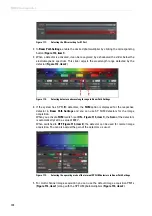
4. Adjust the laser intensity on the laser driver in order to obtain the shortest laser pulse
with respect to measuring instrument response time – "IRF"). In
a second step, adjust the laser intensity on the laser or the laser coupling module (LCU)
(
), to carry out a corresponding adjustment with respect to the correct
fluorescence count rate for FLIM detection.
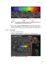
5. Close the shutter of the continuous wave VIS laser in Beam Path Settings and move all
AOTF sliders to the 0 position.
6. Open the shutter for pulsed lasers by turning the button to
ON
).
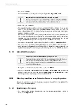
7. Activate the desired laser by moving the corresponding slider up all the way (
).
In the control field of the pulsed lasers, the slider setting does not affect the laser intensity.
The laser intensity is controlled outside the LAS AF on the laser driver (PDL800, SEPIA) and
on the laser coupling module.
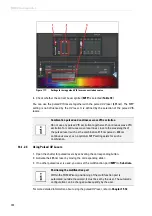
8. Make sure that the multifunction port (
MFP
,
) is in the right position
Figure 104:
Settings for pulsed VIS lasers in Beam Path Settings
Observe the user manuals provided
Always observe all of the user manuals provided for the individual
components and peripheral devices.
Summary of Contents for TCS SP8 SMD
Page 1: ...10 Living up to Life User Manual Leica TCS SP8 SMD for FCS FLIM and FLCS ...
Page 4: ...4 Copyright ...
Page 14: ...14 Contents ...
Page 18: ...18 Intended Use ...
Page 20: ...20 Liability and Warranty ...
Page 28: ...28 General Safety Notes ...
Page 32: ...32 Additional Notes on Handling the System ...
Page 44: ...44 System Overview and Properties ...
Page 60: ...60 SMD Components Figure 31 DSN 102 Dual SPAD Power Supply ...
Page 80: ...80 Safety Features ...
Page 102: ...102 Switching On the System ...
Page 116: ...116 LAS AF ...
Page 214: ...214 Changing the Specimen ...
Page 216: ...216 Changing the Objective ...
Page 238: ...238 Switching Off the System ...
Page 242: ...242 Repairs and Service Work ...
Page 244: ...244 Maintenance ...
Page 246: ...246 Disassembly and Transport ...
Page 248: ...248 Disposal ...
Page 254: ...254 Contact ...
Page 256: ...256 Recommended Literature ...
Page 266: ...266 Appendix Figure 225 Declaration of conformity ...
Page 268: ...268 Appendix ...
Page 269: ......


