179
F(L)CS Data Acquisition
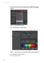
7. Select one (or more) suitable laser line(s) (
) and a suitable detection
range on the detector (
),
8. Then specify the
xyz
mode and a scan speed of 400 Hz for an image.
9. Select
Glow (O&U)
in the color look-up table (LUT).
10. Click
Calibration
in the pull-down menu (
).
A window appears for the calibration procedure (
). The system automatically
determines the following values: Zoom 32 and pixel format 1024x1024.
11. Start a continuous scan by clicking the
Live
) and manipulate
the
Gain
and
Offset
on the control panel to obtain a well-illuminated image.
Figure 155:
Procedure for calibrating the FCS measurement position – Definition of instrument
parameter settings
12. With
Define bleach time
, enter the bleaching period; The default value is 100 ms
). For thin and easily bleached specimens, it may be more useful to
select a bleaching period of 500 ms or shorter.
13. Now select the
Calibrate
).
An image will be acquired automatically. Then, the previously selected laser lines will
automatically be set to 100 % AOTF transmission for photobleaching, and the laser will
bleach in the middle of the image for the set time. Then, another image will be acquired with
the settings made previously.
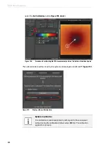
14. Now position the crosshair in the middle of the bleach point (
) and
Summary of Contents for TCS SP8 SMD
Page 1: ...10 Living up to Life User Manual Leica TCS SP8 SMD for FCS FLIM and FLCS ...
Page 4: ...4 Copyright ...
Page 14: ...14 Contents ...
Page 18: ...18 Intended Use ...
Page 20: ...20 Liability and Warranty ...
Page 28: ...28 General Safety Notes ...
Page 32: ...32 Additional Notes on Handling the System ...
Page 44: ...44 System Overview and Properties ...
Page 60: ...60 SMD Components Figure 31 DSN 102 Dual SPAD Power Supply ...
Page 80: ...80 Safety Features ...
Page 102: ...102 Switching On the System ...
Page 116: ...116 LAS AF ...
Page 214: ...214 Changing the Specimen ...
Page 216: ...216 Changing the Objective ...
Page 238: ...238 Switching Off the System ...
Page 242: ...242 Repairs and Service Work ...
Page 244: ...244 Maintenance ...
Page 246: ...246 Disassembly and Transport ...
Page 248: ...248 Disposal ...
Page 254: ...254 Contact ...
Page 256: ...256 Recommended Literature ...
Page 266: ...266 Appendix Figure 225 Declaration of conformity ...
Page 268: ...268 Appendix ...
Page 269: ......


