136
FLIM Data Acquisition
acquisition is applied to the detectors. In other words, the gain cannot be changed as long
as
FLIM
is selected.
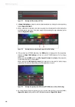
3. Select a suitable range for spectral detection by adjusting the spectral sliders of the SP
FLIM detectors accordingly (
Figure 120, item 2 and 3
).
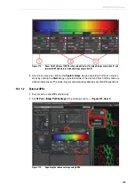
At the same time, additional detectors can be activated and used for intensity image
acquisition. The data of these additional detectors is used for the intensity image
acquisition, but not for FLIM.
4. If you do not obtain an image, check that the X1 port is in the
Mirror
position.
5. Check to ensure that the fluorifier disc is in a suitable position that blocks excitation light
(see
).
16.2.1.2
FLIM Data Acquisition with External MPD APDs
Proceed as follows to prepare the TCS SP8 for collecting FLIM data using external APDs:
1. Switch the APDs on electrically.
2. Select a suitable spectral range for the detection by choosing the appropriate SMD filter
cube and mount it in the X1 port adapter (see
).
3. Open the
Setup
tab.
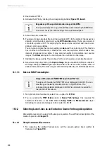
4. In the
FLIM detector
pull-down menu, select the
External
option (
). In
Beam Path Settings
, the APDs should be selected automatically (
).
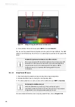
Overload protection for internal SP FLIM detectors
If too much light strikes a FLIM detector, it is temporarily switched off to
prevent damage and automatically switched back on after a few
seconds. If the detector count rate is not reduced, the detectors will
continuously switch off and back on, resulting in horizontal streaks in the
image.
The overload protection of the internal FLIM detectors is active in FLIM
mode and image acquisition mode. To avoid streaking, reduce the
detector count rate. This can be done in a number of ways:
• Reduce the laser intensity
• Reduce the
Gain
(possible in image acquisition mode only)
• Reduce the
Pinhole
• Use specimens with less intensive fluorescent dye
Summary of Contents for TCS SP8 SMD
Page 1: ...10 Living up to Life User Manual Leica TCS SP8 SMD for FCS FLIM and FLCS ...
Page 4: ...4 Copyright ...
Page 14: ...14 Contents ...
Page 18: ...18 Intended Use ...
Page 20: ...20 Liability and Warranty ...
Page 28: ...28 General Safety Notes ...
Page 32: ...32 Additional Notes on Handling the System ...
Page 44: ...44 System Overview and Properties ...
Page 60: ...60 SMD Components Figure 31 DSN 102 Dual SPAD Power Supply ...
Page 80: ...80 Safety Features ...
Page 102: ...102 Switching On the System ...
Page 116: ...116 LAS AF ...
Page 214: ...214 Changing the Specimen ...
Page 216: ...216 Changing the Objective ...
Page 238: ...238 Switching Off the System ...
Page 242: ...242 Repairs and Service Work ...
Page 244: ...244 Maintenance ...
Page 246: ...246 Disassembly and Transport ...
Page 248: ...248 Disposal ...
Page 254: ...254 Contact ...
Page 256: ...256 Recommended Literature ...
Page 266: ...266 Appendix Figure 225 Declaration of conformity ...
Page 268: ...268 Appendix ...
Page 269: ......


